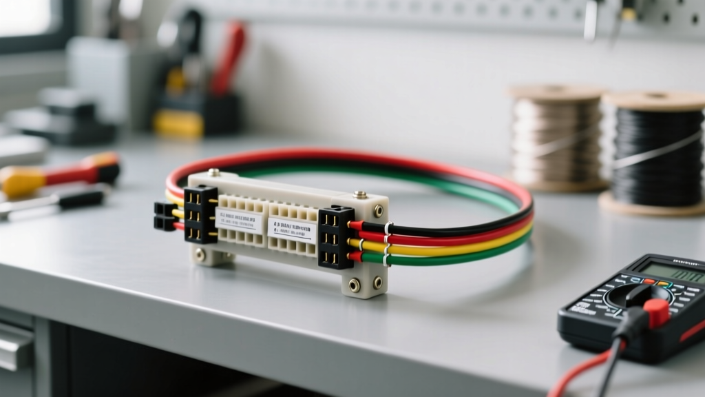
Understanding the 4-Pin Wiring Harness Diagram
When integrating trailer lighting, auxiliary work lights, or custom rear-end setups, the 4-way flat connector remains the automotive industry standard. Governed by the SAE J286 standard, the 4-pin wiring harness diagram relies on a simple, standardized color code to deliver power and ground to exterior lighting. However, modern vehicle architectures—specifically those utilizing Pulse Width Modulation (PWM) and multiplexed CAN-bus taillight circuits—have transformed what was once a simple splice-and-tape job into a complex diagnostic challenge.
As an automotive electrical specialist, relying on a basic test light is no longer sufficient. Improper testing can fry a $300 OEM taillight converter module or trigger anti-theft lockouts. This guide provides a rigorous, step-by-step troubleshooting flow to isolate faults within your 4-pin wiring harness, from the vehicle-side connector to the trailer ground ring.
Standard 4-Pin Flat Harness Pinout & Specifications
| Pin Position | Wire Color | Standard AWG | Circuit Function | Max Continuous Load |
|---|---|---|---|---|
| 1 (Ground) | White | 16 AWG (12 AWG preferred) | Chassis Ground Return | 15A - 20A |
| 2 (Tail/Running) | Brown | 18 AWG | Taillights, Marker Lights | 7.5A |
| 3 (Left Turn/Stop) | Yellow | 18 AWG | Left Turn Signal & Brake | 7.5A |
| 4 (Right Turn/Stop) | Green | 18 AWG | Right Turn Signal & Brake | 7.5A |
Phase 1: Pre-Diagnostic Visual & Physical Inspection
Before connecting a Digital Multimeter (DMM), perform a physical audit of the harness. Over 60% of 4-pin harness failures stem from mechanical and environmental degradation rather than electrical shorts.
- Pin Tension Check: Inspect the female cavities on the vehicle side and male blades on the trailer side. Use a small pick to gently test tension. If a blade slides in without resistance, the internal copper beryllium spring clip has fatigued, leading to micro-arcing and voltage drop under load.
- Dielectric Grease Application: Verify that marine-grade dielectric grease is applied over the mated connection to seal out moisture. Never pack grease inside the pin cavities before mating, as it acts as an insulator and increases resistance.
- Ground Ring Terminal Audit: The white ground wire must terminate to bare, unpainted steel or aluminum. Inspect for galvanic corrosion (white powdery residue) under the ring terminal. If present, remove the terminal, sand the chassis to bare metal with 80-grit sandpaper, apply a zinc-rich cold galvanizing compound, and re-torque using a star washer.
Phase 2: Step-by-Step Multimeter Troubleshooting Flow
Set your high-impedance DMM (minimum 10 Megohm input) to DC Volts. Never use an incandescent test light on modern vehicles equipped with powered converter modules, as the initial current spike can damage the module's internal MOSFETs.
Symptom A: Complete Harness Failure (No Lights on Trailer)
Step 1: Isolate the Ground Circuit (White Wire)
- Connect the DMM's black probe to a known good vehicle chassis ground (e.g., bare suspension bolt).
- Connect the red probe to the white ground pin on the vehicle-side 4-pin connector.
- Turn on the vehicle's running lights and hazard flashers.
- Diagnostic Result: If you read more than 0.1V on the white wire, your vehicle-side ground is compromised. The harness is attempting to backfeed ground through the signal wires. Clean and re-terminate the white wire ground ring immediately.
Step 2: Verify Power Delivery at the Vehicle Connector
- Move the red probe to the brown (tail), yellow (left), and green (right) pins while actuating the corresponding vehicle switches.
- Diagnostic Result: If voltage is present at the vehicle connector but absent at the trailer plug, you have an open circuit (broken wire) or high-resistance splice in the trailer harness. Proceed to Phase 3.
- Diagnostic Result: If voltage is zero at the vehicle connector, the fault lies upstream in the vehicle's taillight converter module, blown fuse, or CAN-bus integration harness.
Symptom B: Dim, Flickering, or Voltage Drop Issues
Dim LED arrays or flickering incandescent bulbs indicate a voltage drop exceeding acceptable thresholds. According to etrailer's comprehensive wiring guidelines, a healthy 12V lighting circuit should not experience a voltage drop greater than 0.2V on the power side, and 0.1V on the ground side.
- Perform a Voltage Drop Test: With the circuit under load (lights turned ON), place the DMM red probe on the battery positive terminal and the black probe on the trailer light's positive feed wire.
- Analyze the Reading: A reading of 1.5V or higher indicates severe resistance. This is typically caused by undersized wiring (using 20 AWG instead of 18 AWG) or corroded butt-splices hidden inside the harness loom.
- The Fix: Cut out all standard vinyl-taped butt connectors. Replace them with adhesive-lined polyolefin heat shrink crimps, and ensure the main harness trunk is upgraded to at least 14 AWG if the trailer exceeds 20 feet in length to mitigate resistance over distance.
Symptom C: Cross-Talk and Backfeeding (Brakes Trigger Turn Signals)
If applying the brakes illuminates the turn signals, or if turning on the running lights causes the brake lights to dimly glow, you are experiencing cross-talk. This is rarely a harness short; it is almost always a failing isolation diode inside the vehicle's 4-pin converter module.
- Cause: Modern vehicles use combined stop/turn bulb circuits. The converter module separates these into distinct outputs for the 4-pin wiring harness diagram. When internal diodes overheat and fail, current backfeeds across the yellow and green circuits.
- Action: Unplug the 4-pin harness from the vehicle. Use the DMM in Continuity/Ohm mode to test between the yellow and green pins on the vehicle-side connector. If you read continuity (near 0 ohms) with the ignition OFF, the converter module is internally shorted and must be replaced. Do not attempt to repair the potted module.
Phase 3: Advanced PWM Converter Module Diagnostics
Vehicles from 2015 onward (such as the F-150, Silverado, and RAM platforms) utilize Pulse Width Modulation (PWM) to monitor bulb health. The BCM (Body Control Module) rapidly pulses the taillight circuit to check for filament resistance. If you hardwire a standard 4-pin harness directly into a PWM wire without a powered isolation module, the BCM will interpret the trailer's low resistance as a short circuit, shutting down the taillight output entirely.
Troubleshooting PWM Shutoff:
- Verify that your 4-pin harness utilizes a powered converter module. A powered module draws lighting current directly from the vehicle battery via a dedicated 12V constant feed (usually a red 12 AWG wire with a 20A inline fuse), using the vehicle's taillight wires only as low-current signal triggers.
- Check the inline fuse on the red 12V battery feed wire. A blown fuse here will result in a dead 4-pin output, even if the vehicle's taillights are functioning perfectly.
- Inspect the signal splice points. Use a logic probe or oscilloscope to verify that the PWM signal is reaching the converter module's input wires. If the module receives the signal but outputs nothing, verify the module's ground wire is secured to a clean, bare metal surface. A poor ground will prevent the module's internal relays from engaging.
Harness Repair Best Practices
When repairing a damaged section of a 4-pin wiring harness, abandon electrical tape and liquid electrical tape. These methods trap moisture and accelerate copper oxidation (the green crust that increases resistance). Instead, utilize the following professional repair sequence:
- Strip 3/8" of insulation using precision wire strippers to avoid nicking the copper strands.
- Use a ratcheting crimp tool with nickel-plated, adhesive-lined heat shrink butt splices.
- Apply heat evenly until the adhesive purges from both ends of the shrink tube, creating a watertight seal.
- Wrap the repaired harness section in Tesa cloth automotive harness tape to prevent abrasion against the chassis, securing it with UV-resistant zip ties every 12 inches.
By adhering to this systematic troubleshooting flow and referencing the precise 4-pin wiring harness diagram specifications, you can eliminate electrical gremlins, protect sensitive vehicle modules, and ensure reliable lighting operation in all weather conditions. For further integration schematics, consult the Hopkins Manufacturing wiring guides for vehicle-specific plug-and-play adapter layouts.