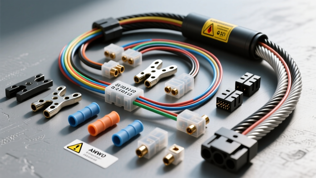
The Hidden Dangers of GM Power Seat Harness Swaps
When integrating late-model General Motors seating into a custom build, resto-mod, or older platform, enthusiasts frequently search for a wiring harness GM power seat wiring diagram to simplify the process. However, GM power seats—particularly from the GMT800 (1999-2006) and GMT900 (2007-2014) Silverado, Tahoe, and Suburban platforms—are not simple 12V motor setups. They are complex, multiplexed electrical nodes. The under-seat wiring harness integrates high-amperage motor feeds, Pulse Width Modulated (PWM) heated/ventilated circuits, CAN-bus memory modules, and critical Supplemental Inflatable Restraint (SIR) airbag systems.
Treating a modern GM seat harness like a basic 4-way bench seat is a primary cause of melted connectors, parasitic battery drains, and in severe cases, electrical fires. This guide outlines the most common wiring mistakes, critical safety warnings, and the exact specifications required to safely wire a GM power seat harness.
Mistake #1: Undersizing High-Current Feeds (The AWG Trap)
The most frequent and dangerous mistake occurs when builders use generic 16 AWG or 14 AWG wiring kits to power GM seat tracks. GM power seat motors draw significant stall current when binding or adjusting under load. The factory wiring harness utilizes 10 AWG (and occasionally 8 AWG for fully loaded heated/ventilated/memory configurations) for the primary Battery Positive and Ground circuits.
The Consequence of Voltage Drop
If you use 16 AWG wire to feed a GM 6-way power seat, the voltage drop over a standard 6-foot run from the fuse panel will cause the motors to pull higher amperage to compensate for the lack of voltage. This excessive current generates severe heat at the Delphi GT 280 series terminals. The plastic connector housing will melt, fusing the pins and creating a high-resistance short that can ignite the carpet insulation.
- Expert Fix: Always use a minimum of 10 AWG wire for the main 12V+ (Orange) and Ground (Black) feeds. Use SAE J1128 Cross-Linked Polyethylene (XLPE) primary wire, which offers superior heat and abrasion resistance compared to standard PVC automotive wire.
- Circuit Protection: Wire the main feed through a 30A maxi-fuse or a GM-style thermal circuit breaker, located within 12 inches of the battery or main distribution block.
Mistake #2: Misinterpreting the Memory Seat Module (MSM) and CAN-Bus
For GMT900 platforms and higher-trim GMT800s, the seat harness includes low-current data lines (GMLAN or Class 2 Serial Data) that communicate with the Memory Seat Module (MSM) and the Body Control Module (BCM). A common error is splicing into these data wires thinking they are 12V accessory feeds, or leaving the MSM powered constantly without its CAN-bus gateway.
The Parasitic Drain Failure Mode
The MSM relies on a CAN-bus "wake up" signal from the door switch or ignition. If you wire the Memory Seat Module to a constant 12V source without the network gateway, the module will never enter sleep mode. This results in a parasitic draw of 150mA to 300mA, which will drain your vehicle's battery dead within 48 hours.
- Expert Fix: If you are swapping memory seats into a non-GM vehicle or an older classic without a compatible BCM, do not connect the CAN-bus lines. Instead, bypass the MSM entirely and wire the 6-way seat track motors directly to heavy-duty DPDT (Double Pole Double Throw) rocker switches using 12 AWG wire.
GM Power Seat 14-Pin / 22-Pin Connector Reference Table
Below is a reference table for the common under-seat Delphi connectors found on GMT800/900 platforms. Always verify against your specific factory service manual, as pinouts vary by RPO (Regular Production Option) codes like A45 (Memory Seat) or KA1 (Heated Seats).
| Pin / Cavity | Wire Color | AWG Size | Function / Circuit | Safety Warning |
|---|---|---|---|---|
| Pin A / 1 | Orange | 10 AWG | Battery Positive (Hot at all times) | Main feed. Requires 30A breaker. |
| Pin B / 2 | Black | 10 AWG | Main Chassis Ground (G201/G202) | Critical. Poor ground causes backfeed. |
| Pin C / 3 | Yellow | 18 AWG | SIR (Airbag) / Pretensioner Feed | DANGER: DO NOT PROBE. Deployment risk. |
| Pin D / 4 | Yellow/Black | 18 AWG | SIR (Airbag) Return / Diagnostic | DANGER: Isolate and cap off if unused. |
| Pin E / 5 | Light Green | 14 AWG | Heated Seat Element Feed (PWM) | Requires factory thermistor & controller. |
| Pin F / 6 | Purple/White | 18 AWG | Heated Seat Thermistor Signal | Low voltage signal. Do not apply 12V. |
| Pin G / 7 | Green/White | 20 AWG | CAN-Bus High (GMLAN) | Data line. Requires termination resistor. |
| Pin H / 8 | Green/Black | 20 AWG | CAN-Bus Low (GMLAN) | Data line. Keep away from high current. |
Mistake #3: Bypassing Heated Seat Thermistors
Enthusiasts often attempt to wire GM heated seats by simply running a 12V feed through a toggle switch to the Light Green (Pin E) wire. This is a massive safety hazard. GM heated seat elements are controlled via Pulse Width Modulation (PWM) to regulate temperature. More importantly, the circuit relies on a negative temperature coefficient (NTC) thermistor (Pin F) to monitor the pad's heat.
If you apply constant 12V DC without the thermistor feedback loop monitored by the seat controller, the heating pads will exceed 150°F (65°C), potentially melting the leather, scorching the foam, and causing severe burns to the occupant. According to SAE wiring standards and automotive safety protocols, heated seat circuits must never be operated in an open-loop configuration.
- Expert Fix: If you must retain heated seats in a custom swap, purchase an aftermarket standalone heated seat controller (such as those from Rostra or Dorman) that includes its own PWM relay and independent thermistor pads. Splice the new thermistor into the seat pad and ignore the factory GM thermistor wiring.
Mistake #4: Neglecting the G200 Series Grounding Strategy
In GM trucks and SUVs, the driver seat relies on ground point G201 (located under the driver's carpet, bolted to the floor pan), and the passenger seat uses G202. When swapping these seats into a fiberglass-bodied vehicle, a tube-frame chassis, or a classic car with poor body-to-chassis grounding, builders often just run a small ground wire to a nearby seat bolt.
The BCM Backfeed Disaster
Seat motors require a massive, low-resistance path to ground. If the ground is restricted, the returning current will seek the path of least resistance. In modern GM harnesses, this backfeed travels backward through the low-current CAN-bus lines or memory switch signal wires, directly into the Body Control Module (BCM) or Door Control Module (DCM). This will instantly fry the BCM's internal logic board, resulting in a $600+ replacement and a vehicle that will not start due to Passlock/VATS security failures.
- Expert Fix: Run a dedicated 10 AWG ground wire from the seat harness directly to a clean, bare-metal point on the main chassis frame. Use a star washer to bite through any powder coating or rust, and torque the ground bolt to factory specifications (typically 9-12 Nm) to prevent vibration loosening.
Critical Safety Warnings: The Yellow SIR Connectors
Every GM power seat wiring diagram will feature Yellow connectors or Yellow wire looms. This is the universal automotive color code for the Supplemental Inflatable Restraint (SIR) system, which includes the seat-mounted side-impact airbags and the seat belt pretensioners.
- Never Probe Yellow Wires: Never use a multimeter, test light, or jumper wire to probe a yellow wire or its connector. The internal resistance of some multimeters can provide enough current to trigger the squib in the pretensioner, causing it to deploy violently in your face.
- Shorting Bars: GM SIR connectors contain internal shorting bars. When you unplug the yellow connector under the seat, the shorting bar bridges the high and low circuits to prevent accidental deployment from static electricity. Do not attempt to bypass or remove these shorting bars.
- Battery Disconnect Protocol: Before cutting, splicing, or manipulating any GM under-seat harness, disconnect the negative battery terminal and wait a minimum of 10 minutes. This allows the backup capacitors in the Sensing and Diagnostic Module (SDM) to discharge completely.
Summary: Best Practices for Custom Harness Fabrication
Successfully integrating a GM power seat requires respecting the distinct separation between high-amperage motor circuits, sensitive data networks, and life-saving SIR systems. Always use SAE J1128 XLPE wire in 10 AWG for power and ground, isolate the memory module if the CAN-bus is absent, and treat all yellow SIR wiring as a non-serviceable, isolated zone. By following these parameters, you ensure a reliable, fire-free installation that maintains the full functionality and safety of your seating system.