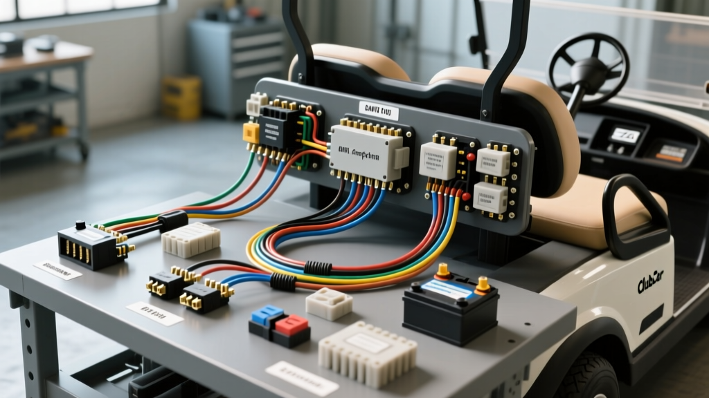
Introduction to Golf Cart Electrical Architecture
Understanding your golf cart wiring harness is the first step toward mastering DIY maintenance, troubleshooting, and accessory upgrades. Whether you are working on a 36V Club Car DS, a 48V EZGO Express, or a Yamaha Drive, the underlying electrical principles remain remarkably consistent. A golf cart wiring harness is not just a single bundle of wires; it is a carefully routed network divided into two distinct subsystems: the high-current traction harness and the low-current signal and accessory harness. For beginners, confusing these two systems is the most common cause of blown fuses, melted connectors, and controller damage.
This guide breaks down the fundamentals of golf cart harnesses, detailing wire gauges, standard color codes, connector types, and real-world troubleshooting techniques. By the end of this article, you will be able to read a wiring diagram, safely tap into your cart's electrical system, and identify common harness failure points.
Anatomy: Traction Harness vs. Signal Harness
The High-Current Traction Harness
The traction harness is responsible for moving the vehicle. It routes massive amounts of direct current (DC) from the battery bank to the main solenoid, the motor controller, and finally the drive motor. In a standard 48V system, this circuit can pull upwards of 300 to 400 amps under heavy load or steep inclines. Because of this extreme amperage, the traction harness utilizes heavy-gauge, heavily insulated cables. These cables are typically routed along the frame rails, away from moving steering components, and are secured with heavy-duty P-clamps or loom clips.
The Low-Current Signal and Accessory Harness
The signal harness acts as the 'nervous system' of the golf cart. It carries low-amperage current (usually under 15 amps) to trigger the solenoid, read the throttle position sensor (TPS), operate the forward/reverse microswitches, and power the On-Board Computer (OBC) or lighting circuits. This harness is bundled in corrugated plastic loom or braided sleeving and features multiple multi-pin connectors that plug into the controller and dashboard.
Wire Gauge (AWG) Specifications and Applications
Selecting the correct American Wire Gauge (AWG) is critical. Using a wire that is too thin for a high-current circuit will result in excessive resistance, voltage drop, and potentially an electrical fire. According to the SAE J1127 standard for battery cables, automotive primary wire must handle specific thermal and amperage loads. Below is a reference chart for standard golf cart harness applications, cross-referenced with industry ampacity guidelines from Del City Wire.
| Circuit Application | Recommended AWG | Max Amperage (Approx) | Insulation Type |
|---|---|---|---|
| Main Battery Interconnects | 2/0 AWG | 350A - 400A | EPDM / Cross-linked Polyethylene |
| Controller to Motor Cables | 4 AWG or 2 AWG | 200A - 250A | High-Temp Thermoplastic |
| Solenoid to Controller B+ | 6 AWG | 120A - 150A | Standard Automotive Primary |
| Headlights / LED Light Bars | 14 AWG | 15A - 20A | PVC / GXL |
| Throttle Sensor / Microswitches | 18 AWG | 3A - 5A | Thin-wall PVC |
Standard Wire Color Codes
While aftermarket harnesses and custom fabrications may deviate, OEM manufacturers like Club Car and EZGO generally adhere to a loose color-code standard for their signal harnesses. Always verify with a digital multimeter (DMM) before cutting or splicing, as previous owners may have altered the wiring.
- Red: Main Battery Positive (B+) or switched 12V/48V power from the key switch.
- Black: Main Ground (B-) or chassis ground.
- Blue: Typically used for the key switch output or the low-speed/forward signal to the controller.
- White: Often designates the high-speed signal, reverse signal, or throttle return ground.
- Yellow: Commonly used for the reverse buzzer circuit or accessory power taps.
- Green: Frequently used for the solenoid coil activation signal or OBC communication lines.
Connector Types and Pin Configurations
The reliability of a golf cart wiring harness relies heavily on its connectors. Vibration, moisture, and battery acid fumes can quickly degrade inferior connections. Here are the three most common connector families you will encounter:
1. Molex MLX Series
Widely used in older EZGO TXT models (both DCS and PDS systems), Molex MLX connectors feature robust, cylindrical pins that handle moderate current (up to 15A per circuit). They are identified by their semi-translucent white or natural nylon housings. When rebuilding these, always use the correct crimp tool to ensure the retention tangs lock securely into the housing.
2. Deutsch DT Series
If you are adding aftermarket accessories like LED light bars or winches, the Deutsch DT connector is the gold standard. Rated for 13 amps per pin, these connectors feature silicone rear grommets and internal O-rings that make them completely waterproof. They are heavily utilized in modern marine and off-road harnesses and are highly recommended for any external accessory tap on a golf cart.
3. AMP Superseal and OEM Controller Plugs
Modern controllers, such as the Club Car Precedent IQ system or Yamaha G29 drives, utilize proprietary, sealed multi-pin connectors (often manufactured by TE Connectivity/AMP). These feature 16-pin or 24-pin configurations with secondary locking wedges (TPA - Terminal Position Assurance). Never force these connectors; if the TPA wedge is not fully seated, the pins will back out when you pull on the harness.
Troubleshooting Common Harness Failures
When a golf cart exhibits electrical gremlins, the wiring harness is often the culprit. Use this symptom-cause-fix decision tree to diagnose common issues:
- Symptom: Cart loses power under heavy load or going uphill, but runs fine on flat ground.
Cause: High resistance in the traction harness due to corroded battery cable lugs or undersized aftermarket cables.
Fix: Perform a voltage drop test across each cable while the cart is jacked up and the wheels are blocked. A healthy 2/0 AWG cable should show less than 0.1V drop under load. Clean terminals with a wire brush and apply dielectric grease. - Symptom: Solenoid clicks rapidly or fails to engage when the pedal is pressed.
Cause: Voltage drop in the 14 AWG or 16 AWG signal wires running from the ignition switch or OBC to the solenoid coil.
Fix: Check the microswitches on the accelerator box. If the switch is good, inspect the harness where it passes through the floorboard or near the steering column, as chafing against the metal frame often grounds the signal wire. - Symptom: Headlights dim when the throttle is pressed.
Cause: Accessories are wired in series with the traction circuit, or the voltage reducer is tapping into a single 8V/12V battery instead of the full pack.
Fix: Rewire the accessory harness to a dedicated 48V-to-12V step-down voltage reducer connected directly to the main pack positive and negative terminals, bypassing the OEM lighting harness entirely.
Upgrading Your Harness for Accessories
One of the most popular beginner projects is installing a street-legal LED light kit, horn, and turn signals. The golden rule of golf cart wiring is never tap high-draw accessories directly into the OEM signal harness. The factory wiring and key switch are typically only rated for 10 to 15 amps total. Adding a 5-amp light bar and a 3-amp horn can easily overload the factory key switch, causing it to melt internally.
Instead, use a heavy-duty relay harness. Run a fused 10 AWG wire directly from the main battery positive to a 30-amp automotive relay. Use the OEM harness (via a fuse tap or add-a-circuit) only to trigger the low-amperage relay coil. This ensures your factory golf cart wiring harness remains safe and unburdened, while your accessories receive full, uninterrupted voltage.
Conclusion and Safety Protocols
Working on a golf cart wiring harness requires respect for the massive current stored in the battery bank. A 48V system can deliver thousands of amps in a dead short, which can instantly weld a wrench to the frame and cause severe burns or fires. Always disconnect the main negative battery cable before cutting, splicing, or routing any new harnesses. By understanding the separation between traction and signal circuits, adhering to proper AWG sizing, and utilizing waterproof connectors like the Deutsch DT series, you can ensure your golf cart's electrical system remains reliable, safe, and ready for the course or the neighborhood streets.