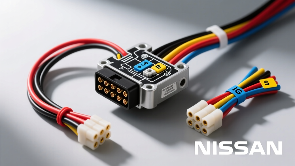
The Z51 VQ35DE Smart Charging System Architecture
The 2009 Nissan Murano (Z51 chassis) equipped with the 3.5L VQ35DE engine utilizes a sophisticated smart charging system managed by the Intelligent Power Distribution Module (IPDM) and the Engine Control Module (ECM). Unlike traditional single-wire alternators that rely on simple internal voltage regulators, the Murano's alternator communicates via a 4-pin Sumitomo-style connector. This setup allows the ECM to monitor the alternator's field duty cycle and adjust the charging voltage dynamically based on electrical load, battery temperature, and engine operating conditions.
Due to the alternator's placement near the rear exhaust crossover and the engine bay's high ambient temperatures, the OEM alternator plug (pigtail) is a notorious failure point. The plastic connector housing becomes brittle, and the internal female terminals lose their tension, leading to arcing, melted housings, and intermittent charging faults. When replacing this harness, selecting the correct pigtail and understanding the 2009 Nissan Murano alternator plug wiring diagram is critical to avoid damaging the ECM or IPDM.
Product Comparison: OEM vs. Aftermarket Alternator Pigtails
When sourcing a replacement pigtail for the 2009 Murano, technicians and DIYers typically choose between Genuine Nissan harnesses and aftermarket solutions from brands like Dorman or Standard Motor Products (SMP). Below is a technical comparison to help you select the right component for your repair.
| Specification | Genuine Nissan OEM | Dorman (Aftermarket) | Standard Motor Products (SMP) |
|---|---|---|---|
| Wire Insulation | XLPE (Cross-linked) | PVC (Standard) | XLPE (High-Temp) |
| Terminal Material | Copper Alloy, Tin-Plated | Brass, Tin-Plated | Copper Alloy, Tin-Plated |
| Weather Seals | Individual Silicone Ribbed | Universal Silicone | Individual Silicone Ribbed |
| Wire Length | 12 Inches (Exact Match) | 8-10 Inches (Generic) | 12 Inches (Exact Match) |
| Best Use Case | Dealership / Purist Restorations | Budget / Emergency Fixes | Independent Shops / Daily Drivers |
Expert Recommendation: For the Z51 Murano, we highly recommend either the Genuine Nissan harness or the SMP equivalent. The engine bay heat requires XLPE (Cross-linked Polyethylene) wire insulation, which withstands temperatures up to 150°C (302°F). Standard PVC insulation found in cheaper aftermarket pigtails will harden and crack within two years due to radiant heat from the VQ35DE exhaust manifolds. For more on automotive wire insulation standards, refer to the SAE J1128 Low Tension Primary Cable specifications.
2009 Nissan Murano Alternator Plug Wiring Diagram & Pinout
The 2009 Murano alternator connector features four distinct circuits. Miswiring these pins will result in immediate ECM faults, a flashing battery light, or a dead battery. Below is the exact pinout configuration and wire color coding based on the Nissan Factory Service Manual (FSM) wiring schematics.
| Pin Number | Terminal ID | Function | OEM Wire Color | AWG Size | Destination |
|---|---|---|---|---|---|
| 1 | S (Sense) | Battery Voltage Sense | Red / White Stripe | 14 AWG | IPDM / Battery Positive |
| 2 | L (Lamp) | Charge Indicator / Excitation | Yellow / Blue Stripe | 18 AWG | IPDM / Instrument Cluster |
| 3 | G (Ground) | Sensor / Logic Ground | Black | 14 AWG | Engine Block / Chassis Ground |
| 4 | FR (Field) | Field Monitor (PWM Signal) | Green / White Stripe | 18 AWG | ECM (Pin 42 on F103 Connector) |
Understanding the FR (Field) Signal
The FR wire is the most critical circuit in the smart charging system. It sends a Pulse Width Modulated (PWM) square wave signal from the alternator's internal regulator back to the ECM. The ECM reads this duty cycle to determine the alternator's current output load. If the FR wire is severed, spliced with high resistance, or pinned to the wrong terminal, the ECM will default to a fail-safe charging mode (usually locking the alternator at a fixed 13.8V) and will trigger a Diagnostic Trouble Code (DTC) such as P0562 (System Voltage Low) or P0620 (Generator Control Circuit).
Harness Routing and Thermal Protection
The VQ35DE engine generates immense heat, particularly near the firewall and rear exhaust crossover where the alternator is mounted. When installing your new pigtail, proper routing is just as important as the wiring diagram itself.
- Clearance: Ensure the new harness has at least 3 inches of clearance from the exhaust heat shield.
- Conduit: Wrap the new pigtail in high-temperature fiberglass sleeving or corrugated nylon loom rated for 200°C.
- Strain Relief: Use a P-clip to secure the harness to the alternator casing bracket. Leaving the wire hanging solely by the connector tension will cause the Sumitomo terminals to fret and oxidize over time.
Step-by-Step Splicing and Repair Protocol
Never use twist-on wire connectors or standard electrical tape in the Murano's engine bay. Vibration and heat will cause these methods to fail rapidly. Follow this professional splicing protocol:
- Cut and Strip: Cut the damaged OEM harness back to clean, unoxidized copper. Strip exactly 5/16" of insulation from both the chassis harness and the new pigtail.
- Match AWG: Ensure your splice connectors match the wire gauge. Use 14-16 AWG butt connectors for the Sense and Ground wires, and 18-22 AWG connectors for the Lamp and FR wires.
- Crimp and Solder: Use a ratcheting crimping tool (such as the TE Connectivity CERTI-CRIMP) to secure the barrel. For maximum reliability in smart-charging signal wires (FR and L), flow a small amount of rosin-core solder into the crimp barrel to eliminate micro-voltage drops.
- Marine Heat Shrink: Seal every splice with dual-wall, adhesive-lined marine heat shrink tubing. The inner meltable adhesive creates a waterproof barrier against engine degreasers and moisture.
Diagnosing IPDM and FR Signal Faults
If you have replaced the pigtail using the correct wiring diagram but the battery light remains illuminated, the issue may lie within the IPDM or the alternator itself. Here is a diagnostic decision tree for post-repair troubleshooting:
- Symptom: Battery reads 12.2V at idle, jumps to 14.2V only when revving past 2,500 RPM.
Cause: The 'L' (Lamp/Excitation) wire is broken or has high resistance. The alternator is not receiving the initial ignition-on excitation voltage from the IPDM to 'wake up' the regulator. - Symptom: Alternator whines, voltage fluctuates wildly between 12.5V and 15.5V.
Cause: The 'S' (Sense) wire is damaged or spliced poorly. The regulator is sensing voltage at the alternator B+ terminal rather than at the battery, causing it to overcompensate for voltage drop across the vehicle's main wiring. - Symptom: DTC P0620 stored in ECM, charging system stuck at 13.8V.
Cause: Loss of the 'FR' PWM signal. Test the FR wire with an oscilloscope or a multimeter set to Duty Cycle. At idle with headlights off, you should see a 20-30% duty cycle. With high electrical load (headlights, blower motor, rear defroster), the duty cycle should increase to 70-90%.
By strictly adhering to the 2009 Nissan Murano alternator plug wiring diagram and utilizing high-temperature, OEM-equivalent materials, you can permanently resolve Z51 charging system gremlins and restore the VQ35DE's smart-charging efficiency. For further diagnostic flowcharts and IPDM relay testing procedures, consult the Nissan TechInfo portal or your local dealership's service department.