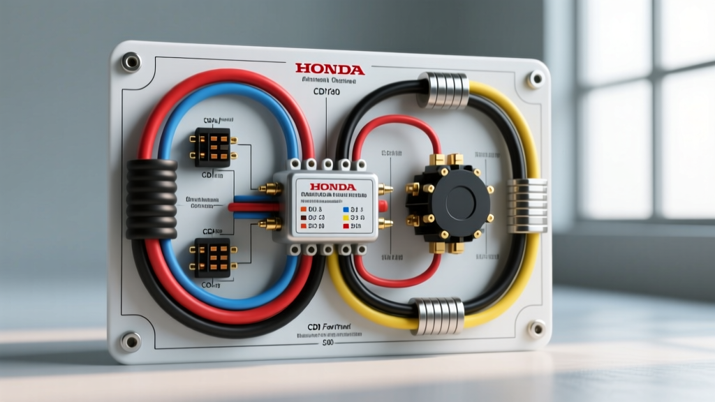
Introduction to the TRX300 Magneto Ignition System
The Honda TRX300 and TRX300FW FourTrax (produced from 1988 to 2000) remain some of the most reliable utility ATVs ever built. However, their electrical systems—specifically the magneto-driven Capacitor Discharge Ignition (CDI)—are notoriously unforgiving when subjected to improper wiring modifications or hasty repairs. Unlike modern fuel-injected machines that rely on a stable 12V battery supply for spark generation, the TRX300 generates its own high-voltage AC current via the stator's exciter coil to fire the spark plug. This means the ignition system operates entirely independently of the 12V battery.
When mechanics and DIY enthusiasts approach the Honda 300 FourTrax ignition wiring diagram with a standard automotive mindset, they frequently make critical errors that result in blown CDI units, melted stator windings, or intermittent no-spark conditions. This guide breaks down the core ignition circuits, highlights the most common wiring mistakes, and provides essential safety warnings to protect both you and your ATV's electrical components.
Critical Safety Warnings Before You Trace a Wire
Working on a magneto-based CDI system presents unique hazards that do not exist on standard 12V automotive systems. Before you unplug a single connector or strip a wire, internalize these safety protocols:
- The Magneto Shock Hazard: Disconnecting the 12V battery does not make the ignition system safe. Because the stator generates its own power, cranking the engine while holding a damaged spark plug wire or touching an exposed CDI pin can deliver a high-voltage shock (up to 30,000V on the secondary side). Always remove the spark plug cap and ground the plug to the cylinder head before cranking the engine during diagnostics.
- Capacitor Discharge Risk: The 'C' in CDI stands for Capacitor. The internal capacitor stores high-voltage DC energy. Even with the engine off and the stator disconnected, a faulty CDI can retain a dangerous charge. Never probe the internal circuitry of a CDI unit.
- Avoid Grounding the Exciter Wire: The Black/Red wire from the stator carries high-voltage AC directly to the CDI. If you accidentally ground this wire to the frame while the engine is being kicked or electric-started, you will instantly short out the stator's exciter winding, requiring a complete stator replacement.
Honda 300 FourTrax Ignition Wiring Diagram: Core Circuit Breakdown
To avoid mistakes, you must understand the path of electrical energy from the stator to the spark plug. The TRX300 ignition circuit is divided into three primary stages:
1. Stator to CDI Routing (The AC Generation Stage)
Inside the left-side engine cover, the stator features two distinct ignition windings: the Exciter Coil and the Pulse Generator. The Exciter Coil (Black/Red wire) generates the raw AC voltage (typically 100V to 400V depending on RPM) that charges the CDI's internal capacitor. The Pulse Generator (Blue/Yellow wire) reads the magnetic pickup on the flywheel, sending a low-voltage signal (0.5V - 2.0V) to the CDI's thyristor, telling it exactly when to fire.
2. The CDI Logic & Kill Circuit
The CDI unit receives the high voltage, rectifies it, and stores it. When the Pulse Generator sends the trigger signal, the CDI's Silicon Controlled Rectifier (SCR) opens, dumping the stored voltage into the ignition coil's primary winding. The TRX300's engine stop (kill) switch works by grounding the CDI's internal circuit. When you press the kill switch, the Black/Yellow wire is bridged to the Green (ground) wire, safely bleeding off the exciter voltage before it can reach the capacitor.
3. Ignition Coil & Secondary Output
The Black/White wire carries the primary pulse from the CDI to the ignition coil. The coil steps this voltage up from roughly 300V to over 25,000V, sending it through the spark plug wire to ignite the air/fuel mixture.
The 5 Most Common Wiring Mistakes (And How to Fix Them)
Based on decades of field diagnostics, these are the most frequent errors made when interpreting the Honda 300 FourTrax ignition wiring diagram.
Mistake 1: Confusing the Lighting Coil (White) with the Exciter (Black/Red)
The Error: The stator outputs a White wire for the lighting/charging circuit and a Black/Red wire for the ignition exciter. Because both originate from the stator and carry AC voltage, novice mechanics sometimes splice the White wire into the CDI's Black/Red input to 'boost' spark.
The Result: The lighting coil outputs up to 80+ VAC at high RPMs, but it lacks the specific frequency and amperage profile required by the CDI. More importantly, splicing the lighting circuit into the CDI will cause a massive backfeed, instantly frying the CDI's internal diode bridge and SCR.
The Fix: Never intermingle the lighting (White/Yellow) and ignition (Black/Red/Blue) stator circuits. If the Black/Red wire is damaged, replace the stator or use SAE J1128 compliant high-temperature primary cable to repair it.
Mistake 2: Using Standard Butt Splices on the Pulse Generator
The Error: The Blue/Yellow pulse generator wire carries a millivolt signal. Mechanics often repair a broken Blue/Yellow wire using standard, non-waterproof crimp butt splices.
The Result: The TRX300 is frequently exposed to mud and water. Standard crimps corrode rapidly, introducing resistance. Because the pulse signal is so weak (under 2V), even 5 ohms of corrosion resistance will drop the signal below the CDI's trigger threshold, causing the engine to randomly die when hitting a puddle.
The Fix: Always use marine-grade, heat-shrink solder seals for any pulse generator or CDI wiring repairs. Alternatively, replace the entire wiring harness pigtail using OEM Honda connectors.
Mistake 3: Grounding the CDI to a Painted Frame Rail
The Error: Extending the CDI's Green ground wire and bolting it to a painted section of the ATV's frame or a rusty fender bolt.
The Result: The CDI requires an absolute, zero-resistance ground to properly discharge the capacitor and trigger the SCR. A painted frame introduces variable resistance, leading to weak spark, misfires at high RPM, or complete failure to start.
The Fix: The Green wire must be grounded directly to the battery negative terminal or a clean, bare-metal grounding lug on the engine block. Use a minimum of 14 AWG wire for extended ground runs.
Mistake 4: Bypassing the OEM Kill Switch with a Toggle Switch
The Error: When the OEM handlebar kill switch corrodes, owners often bypass it by wiring a cheap automotive toggle switch between the Black/Yellow wire and the frame.
The Result: Automotive toggle switches are not sealed. When water enters the switch, it creates a partial ground path. This 'leaks' enough voltage from the exciter coil to weaken the spark, causing the ATV to bog down under load, even when the toggle switch is in the 'Run' position.
The Fix: Clean the OEM switch contacts with electrical contact cleaner. If replacement is necessary, use a sealed, IP67-rated marine rocker switch, and apply dielectric grease to the terminals.
Mistake 5: Incorrect Ignition Coil Primary Wire Routing
The Error: Routing the Black/White primary ignition wire tightly alongside the stator's White lighting wire or the main battery harness.
The Result: The Black/White wire carries a high-voltage spike (up to 300V) back from the CDI. Running it parallel to low-voltage sensor wires or the lighting coil induces Electromagnetic Interference (EMI), which can cause erratic headlight flickering or interfere with aftermarket accessories.
The Fix: Route the Black/White wire directly from the CDI to the ignition coil, keeping it at least 2 inches away from the stator output bundle.
OEM Wire Color Code & CDI Pinout Reference Table
Use this reference table when testing the 5-pin CDI connector on the TRX300. Ensure your multimeter probes are making solid contact with the female terminals without spreading them open.
| CDI Pin | Wire Color | Function | Expected Voltage / Resistance | Wire Gauge (AWG) |
|---|---|---|---|---|
| 1 | Black/Red | Exciter Coil (+) | 100-400 VAC (Running) | 100-500 Ω (Static) | 16 AWG |
| 2 | Blue/Yellow | Pulse Generator (+) | 0.5-2.0 VAC (Cranking) | 90-120 Ω (Static) | 18 AWG |
| 3 | Green | System Ground | 0V | Continuity to Battery (-) | 14-16 AWG |
| 4 | Black/White | Ignition Coil Primary | 12V / 300V Spike | 0.4-0.6 Ω (Coil Primary) | 16 AWG |
| 5 | Black/Yellow | Engine Stop (Kill) | Grounded to Kill | Open to Run | 18 AWG |
Note: Always refer to the official Honda Powersports Service Documentation for your specific model year, as minor harness revisions occurred between the 1988 launch and the 2000 final production year.
Diagnostic Decision Tree: No-Spark Troubleshooting
When your TRX300 has no spark, do not immediately replace the CDI. The CDI is rarely the culprit; the issue usually lies in the switches, grounds, or stator. Follow this sequence:
- Isolate the Kill Circuit: Unplug the main harness connector near the CDI. This bypasses the key switch, handlebar kill switch, and neutral safety switch. Crank the engine. If you now have spark, your ignition circuit is fine, and you have a shorted kill switch or faulty key cylinder grounding the Black/Yellow wire.
- Test the Pulse Generator: Set your Digital Multimeter (DMM) to the 200Ω scale. Probe the Blue/Yellow and Green wires at the stator plug. You should read between 90 and 120 ohms at room temperature (68°F/20°C). If it reads 'OL' (Open Loop), the pulse generator is dead and the stator must be replaced.
- Test the Exciter Coil: Set the DMM to the 2KΩ scale. Probe the Black/Red and Green wires. A healthy exciter coil will show 100 to 500 ohms. A reading of zero indicates an internal short; an infinite reading indicates a broken winding.
- Verify the Ignition Coil: Check the primary resistance (Black/White wire to ground) for 0.4 to 0.6 ohms. Check the secondary resistance (spark plug cap to ground) for 7,000 to 11,000 ohms. If the secondary is out of spec, replace the coil and ensure you are using a 5kΩ resistor-type spark plug cap (NGK VD05F) to prevent EMI damage to the CDI.
Final Thoughts on TRX300 Electrical Integrity
The Honda 300 FourTrax ignition system is a masterpiece of 1990s analog engineering, but it demands respect for its specific wiring parameters. By avoiding the temptation to mix lighting and ignition circuits, using proper marine-grade connectors, and strictly adhering to the OEM ground paths, you can ensure your TRX300 continues to fire reliably for decades to come. Always prioritize high-temperature, SAE-compliant wiring when repairing stator outputs, and never bypass the factory safety grounds.