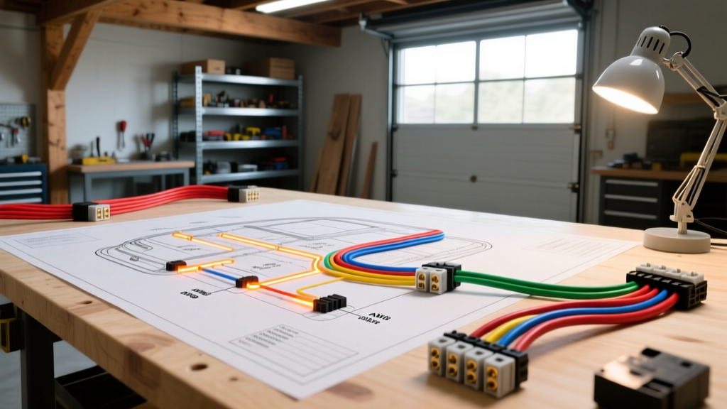
Converting a Backyard Shed into an Automotive Diagnostic Bay
When automotive enthusiasts and mobile mechanics transition from driveway repairs to a dedicated backyard workspace, the standard residential electrical setup is rarely sufficient. An electrical wiring diagram for a shed intended for automotive repair must account for high-draw fabrication tools, sensitive ECU programming equipment, and modern EV charging infrastructure. Standard 15-amp lighting circuits shared with power tools will cause severe voltage sags, which can corrupt data logs or brick a Powertrain Control Module (PCM) during a flash. This complete wiring walkthrough details how to properly design, route, and terminate a 100-amp automotive subpanel tailored specifically for vehicle diagnostics, welding, and EV maintenance.
The Subpanel and Feeder: Sizing for Automotive Loads
The foundation of any automotive shed workshop is the subpanel. To support simultaneous operation of a MIG welder, air compressor, and diagnostic cart, a 100-amp Square D QO or Siemens subpanel is the minimum requirement. The feeder cable from your main residential panel to the shed must be sized to handle continuous loads while mitigating voltage drop over long underground runs.
For a standard 100-foot underground run, utilize 2 AWG Aluminum SER (Service Entrance Rated) cable or individual 2 AWG XHHW-2 conductors pulled through 1.5-inch Schedule 80 PVC conduit. This configuration keeps voltage drop under 3% at maximum load, adhering to the NFPA 70 National Electrical Code recommendations for branch and feeder circuits. The conduit must be buried at least 24 inches deep to protect against future landscaping or heavy vehicle traffic near the shed perimeter.
Zone 1: Clean Power for ECU Flashing and OBD2 Diagnostics
Modern vehicle diagnostics require absolute electrical stability. When flashing a PCM using OEM software like Ford FDRS, GM GDS2, or Chrysler wiTECH, the OBD2 connector relies on Pin 16 for battery positive and Pins 4 and 5 for chassis and signal grounds. If the shed's power fluctuates, or if electromagnetic interference (EMI) from nearby compressors bleeds into the circuit, the CAN bus network can experience packet loss, resulting in U-codes (e.g., U0100 Lost Communication) or a bricked module mid-flash.
To prevent this, the electrical wiring diagram for a shed auto-shop must include a dedicated 20-amp 120V Isolated Ground (IG) circuit specifically for the diagnostic cart and battery maintainer. Use 10 AWG copper THHN wire (oversized from the standard 12 AWG to eliminate resistance over distance) with an orange insulated ground wire run directly back to the subpanel's ground bar, bypassing the metal junction boxes. This isolated ground prevents ground loops and ensures the OBD2 port receives a clean, uninterrupted sine wave, critical for oscilloscope readings and module programming.
Zone 2: Heavy Fabrication, Welding, and Air Compression
Chassis stiffening, exhaust fabrication, and suspension repair require heavy-duty 240V equipment. A typical 210-amp MIG welder and a 60-gallon two-stage air compressor cannot share a breaker. According to the Miller Electric Welder Circuit Guide, a standard 240V welder requires a dedicated 50-amp breaker.
Route a 240V circuit using 6 AWG copper THHN to a NEMA 6-50R receptacle mounted on a reinforced unistrut bracket. This prevents the heavy welder plug from pulling out of the drywall during movement. The air compressor requires its own dedicated 30-amp 240V circuit using 10 AWG copper, terminated at a NEMA 6-30R. Keeping the compressor on a separate circuit ensures that when the motor kicks on to replenish the tank, the resulting inrush current does not dim the overhead lighting or disrupt the diagnostic laptop's power supply.
Zone 3: EV Level 2 Charging Integration
As electric vehicles become more prevalent, integrating a Level 2 EVSE (Electric Vehicle Supply Equipment) into your shed is essential. Adhering to the SAE International J1772 standard and NEC Article 625, a 40-amp continuous EV charger requires a 50-amp breaker (125% sizing rule). Run 6 AWG copper wire through 3/4-inch rigid metal conduit (RMC) along the interior wall to protect the cable from rolling floor jacks and heavy tool chests. Ensure the EVSE is mounted on a structural stud, as the weight of the unit combined with the tension of the heavy-gauge charging cable can easily rip standard drywall anchors out over time.
Automotive Shed Circuit Breakdown & AWG Specifications
| Circuit Zone | Breaker Size | Wire Gauge (AWG) | Receptacle / Termination | Automotive Application |
|---|---|---|---|---|
| Diagnostic / ECU Flash | 20A 120V | 10 AWG Cu (IG) | NEMA 5-20R (Orange) | OBD2 Scanners, PCM Flashing, Oscilloscopes |
| MIG / TIG Welder | 50A 240V | 6 AWG Cu | NEMA 6-50R | Exhaust Fab, Chassis Repair, Subframe Welding |
| Air Compressor | 30A 240V | 10 AWG Cu | NEMA 6-30R | Pneumatic Tools, Impact Wrenches, Sandblasting |
| EV Level 2 Charger | 50A 240V | 6 AWG Cu | Hardwired EVSE | SAE J1772 EV Charging, Battery Balancing |
| High-CRI Lighting | 15A 120V | 14 AWG Cu | LED Drivers | 5000K Harness Inspection, Paint Correction |
Lighting: High-CRI Requirements for Wiring Harness Inspection
Automotive wiring repair demands exceptional visual acuity. Identifying a faded Dark Green/Orange tracer stripe from a Black/Pink stripe inside a 20-year-old engine bay harness is nearly impossible under standard 3000K warm-white shed lighting. Your lighting circuit must utilize 5000K to 6000K LED shop lights with a CRI (Color Rendering Index) of 90 or higher. Wire the lighting circuit on a dedicated 15-amp breaker using 14 AWG wire, completely isolated from the compressor and welder circuits. This ensures that when the air compressor's pressure switch engages, the magnetic ballast or LED drivers do not experience a voltage sag that causes a strobe effect, which can lead to severe eye strain and misdiagnosis of frayed wire insulation.
Grounding, Bonding, and CAN Bus Troubleshooting Matrix
Per NEC 250.32, a detached shed subpanel requires its own Grounding Electrode System (GES). Drive two 5/8-inch copper-clad ground rods, 8 feet deep and spaced 6 feet apart, and tie them to the subpanel ground bar using bare 6 AWG copper wire. A poor ground rod connection will cause the vehicle's chassis (when connected to a chassis-grounded lift or engine hoist) to float relative to the diagnostic equipment, leading to erratic oscilloscope waveforms.
Real-World Shed Troubleshooting Decision Tree
- Symptom: OBD2 Scanner drops connection to the PCM during live data logging or bi-directional testing.
- Cause: Voltage drop on the 120V diagnostic circuit when the shed's air compressor kicks on, pulling system voltage below 11.5V at the laptop's power brick.
- Fix: Verify the diagnostic circuit is on the dedicated 20A IG breaker. Check for loose neutral lugs in the subpanel causing a floating neutral under load.
- Symptom: MIG Welder arc is erratic, wire feeds inconsistently, and welds show excessive porosity on thin automotive sheet metal.
- Cause: Undersized main feeder wire to the shed subpanel causing severe voltage sag under the 240V welder load, or a corroded ground rod connection.
- Fix: Upgrade the main subpanel feeder from 4 AWG to 2 AWG aluminum. Verify tight torque on all bus bar lugs using a calibrated inch-pound torque screwdriver to manufacturer specifications.
- Symptom: Picoscope or Snap-on Modis shows excessive noise/ripple on the CAN High and CAN Low differential pair when the vehicle is plugged into a shed battery maintainer.
- Cause: Cheap, unfiltered switch-mode battery chargers injecting high-frequency EMI back into the shed's grounding system, which transfers through the vehicle's OBD2 Pin 5 signal ground.
- Fix: Use only automotive-grade, high-frequency filtered smart chargers (e.g., CTEK or Schumacher ProSeries) on the isolated ground circuit, and ensure the shed's isolated ground bus is not bonded to the neutral bar in the subpanel.
By treating your shed not as a simple storage outbuilding, but as a professional-grade automotive electrical environment, you protect thousands of dollars in diagnostic equipment and prevent catastrophic module failures during ECU programming. Always consult local codes and a licensed electrician when pulling permits for 100-amp subpanel installations.