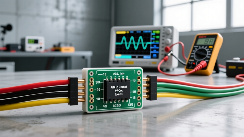
Understanding the GM 2-Wire Variable Reluctance VSS Architecture
When diagnosing drivetrain speedometer faults, erratic shifting, or torque converter clutch (TCC) lockup failures in classic General Motors trucks and SUVs, understanding the GM 2 wire speed sensor wiring diagram is critical. Unlike modern 3-wire Hall-effect sensors that require a 5-volt reference and a dedicated ground, the classic GM 2-wire Vehicle Speed Sensor (VSS) is a Variable Reluctance (VR) transducer. It is entirely self-generating, producing an alternating current (AC) sine wave whose frequency and amplitude scale directly with the rotational speed of the transmission output shaft.
This architecture is predominantly found on GM 4L60E, 4L65E, and 4L80E transmissions from the mid-1990s through the early 2000s (GMT400 and GMT800 platforms). The sensor reads a 40-tooth reluctor ring (tone ring) pressed onto the output shaft inside the transmission tail housing. Because it generates its own analog AC signal, the wiring harness must be treated as a high-impedance, low-voltage antenna circuit, making it highly susceptible to electromagnetic interference (EMI) and parasitic resistance if the OEM routing is compromised.
OEM Wiring Schematic: Sensor to PCM Routing
The routing from the transmission tail housing to the Powertrain Control Module (PCM) relies on a dedicated twisted-pair or shielded circuit to prevent alternator whine and ignition crossfire from corrupting the sine wave. Below is the definitive pinout and wire color reference for the standard 1996–2002 GM 4L60E application utilizing the 80-Way Blue PCM connector (Connector C1).
Circuit Specifications and PCM Pinout Table
| Circuit ID | Wire Color (OEM) | Function | AWG Size | PCM Connector / Pin |
|---|---|---|---|---|
| 400 | Dark Green (DK GRN) | VSS Signal (AC Voltage) | 20 AWG | C1 (Blue) / Pin 21 |
| 401 | Yellow/Black (YEL/BLK) | VSS Signal Return / Low Ref | 20 AWG | C1 (Blue) / Pin 22 |
Note: On some late-model GMT800 applications, Circuit 401 may be Light Blue (LT BLU) or Purple/White (PPL/WHT) depending on the exact RPO code and harness revision. Always verify with a factory service manual for your specific VIN.
Signal Dynamics and Oscilloscope Analysis
To properly interpret a GM 2 wire speed sensor wiring diagram, you must understand the physics of the signal it carries. The VR sensor consists of a permanent magnet encased in a coil of fine copper wire. As the 40-tooth reluctor wheel rotates, the magnetic reluctance of the circuit changes, inducing an AC voltage.
- Amplitude: At idle or very low speeds (e.g., 5 MPH), the AC voltage may be as low as 0.2V to 0.5V. At highway speeds (60+ MPH), the amplitude can exceed 6.0V AC.
- Frequency: The PCM calculates vehicle speed based on frequency, not amplitude. With a 40-tooth reluctor, one revolution of the output shaft yields 40 pulses. At an output shaft speed of 1,000 RPM, the frequency is exactly 666.6 Hz.
When viewing this circuit on a digital storage oscilloscope (DSO), you should see a clean, symmetrical sine wave centered around 0V. If the waveform is clipped, asymmetric, or exhibits high-frequency noise on the peaks, you are likely dealing with EMI intrusion or a damaged reluctor wheel tooth.
Advanced Diagnostic Decision Tree
Before replacing the sensor or tearing into the transmission tail housing, execute this systematic diagnostic sequence to isolate the fault to the sensor, the harness, or the PCM.
Step 1: Static Sensor Resistance Verification
Disconnect the 2-way Metri-Pack 150 connector at the transmission. Set your digital multimeter (DMM) to Ohms (Ω). Measure across the two sensor terminals. A healthy GM VR VSS will read between 900 Ω and 1,200 Ω at room temperature (68°F / 20°C). If the reading is infinite (open) or near zero (shorted internally), the sensor coil has failed and requires replacement.
Step 2: Dynamic AC Voltage Output Test
Reconnect the sensor and back-probe the harness connector using T-pins or specialized piercing probes. Set the DMM to AC Volts. Safely elevate the vehicle and spin the rear wheels (or driveshaft) by hand or at a very low idle in gear (with extreme caution). You should observe a minimum of 0.3V AC at low rotational speeds. If the sensor tests good in Step 1 but generates no AC voltage in Step 2, the reluctor ring may be missing teeth, or the air gap between the sensor tip and the reluctor is excessive due to debris or improper seating.
Step 3: Harness Integrity and Shielding Check
If the sensor generates a valid signal but the PCM is not registering speed (resulting in a P0500 or P0502 DTC), the fault lies in the wiring. Disconnect the PCM C1 connector. Measure the resistance of Circuit 400 (Dark Green) and Circuit 401 (Yellow/Black) from the sensor plug to the PCM pins. Resistance should be less than 1.5 Ω. Next, check for a short to ground on both circuits. Because this is a floating differential signal, neither wire should have continuity to the chassis ground.
Common Failure Modes in GM 4L60E/4L80E Applications
Based on extensive field diagnostics, the most frequent points of failure for the GM 2-wire VSS circuit are mechanical and environmental rather than electrical:
- Harness Chafing at the Crossmember: The OEM harness often rubs against the transmission crossmember or the driveshaft. Over time, the 20 AWG wire insulation degrades, leading to intermittent shorts to ground. This causes the speedometer to drop to zero at specific vehicle speeds or over bumps.
- Terminal Fretting Corrosion: The 2-way weather-pack connector at the tail housing is exposed to road salt, water, and extreme thermal cycling. Micro-vibrations cause fretting corrosion on the brass terminals, introducing parasitic resistance that dampens the low-speed AC voltage signal, preventing the PCM from detecting vehicle movement below 15 MPH.
- Aftermarket EMI Intrusion: Routing the VSS harness parallel to aftermarket high-energy ignition wires or unshielded alternator output cables will induce parasitic AC noise. The PCM's internal signal conditioning filter will reject this noisy signal, setting a rationality fault code.
Best Practices for Harness Repair
When repairing a compromised GM 2 wire speed sensor circuit, never use standard crimp caps or electrical tape. The transmission tunnel environment exceeds 200°F. Use 20 AWG Cross-Linked Polyethylene (XLPE) wire, which is rated for high-temperature automotive environments. Splices must be performed using solder-seal heat shrink butt connectors or ultrasonic welding to ensure a gas-tight, moisture-proof joint. Always re-wrap the repaired section in high-temp Tesa tape or split braided sleeving, and secure it away from moving drivetrain components.
Authoritative References
- AA1Car Automotive Tech Info: Vehicle Speed Sensor (VSS) Diagnostics - Comprehensive guide on VR sensor waveform analysis and circuit testing.
- SAE International J1113: Electromagnetic Compatibility Standards - Reference for wiring harness routing, shielding requirements, and EMI mitigation in automotive sensor circuits.
- General Motors Service Information (GMSI) - OEM Wiring Schematics and Pinout Matrices for GMT400/800 4L60E Powertrain Control Modules.