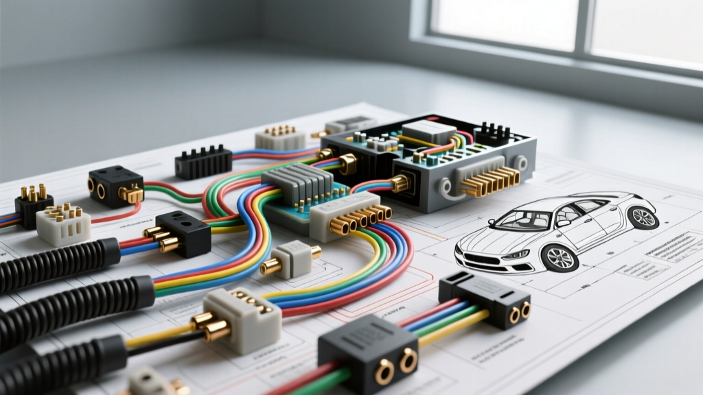
The Hidden Dangers in the Wiring Diagram for ATS Models
The Cadillac ATS (2013-2019) represents a masterclass in GM's Global A electrical architecture, featuring highly integrated multiplexed networks, sensitive Body Control Modules (BCM), and precision engine management systems. However, this complexity means that misinterpreting a wiring diagram for ATS vehicles can lead to catastrophic module failures, untraceable parasitic draws, and severe safety hazards. Many technicians and DIY enthusiasts approach these schematics as simple point-to-point continuity maps, ignoring the critical legends, shielded wire requirements, and splice pack limitations embedded in the documentation.
When working on the ATS platform, a single probing error on a high-speed data bus or an improper splice on a ground circuit can cascade into thousands of dollars in module replacements. This guide outlines the most common, destructive mistakes made when utilizing ATS wiring schematics and provides the actionable, safety-critical protocols required to diagnose and repair these vehicles correctly.
Decoding the Schematic Legends: The First Line of Defense
Before tracing a single wire, you must understand GM-specific schematic symbols. A frequent mistake is assuming a standard dot on a wiring line indicates a splice. In GM Global A schematics, a solid black dot indicates a physical splice pack or solder joint, while a white dot with a crosshair indicates a connector cavity. Misidentifying these leads to tearing apart harnesses searching for splices that exist only inside a connector housing. Furthermore, the wiring diagram for ATS models uses specific line styles: a dashed line indicates a shielded wire or a twisted pair, while a thick solid line denotes high-current battery or ground feeds. Ignoring the dashed line notation is a primary cause of Electromagnetic Interference (EMI) issues post-repair.
Mistake #1: Fatal Probing Errors on GMLAN / CAN Bus Circuits
The Cadillac ATS relies heavily on High-Speed GMLAN (CAN) for critical powertrain and chassis communication. The Engine Control Module (ECM) communicates via Connector X2. A devastatingly common mistake is using a standard 12V incandescent test light or a low-impedance multimeter to probe CAN High and CAN Low circuits for 'power'.
The Reality: CAN bus transceivers operate on milliamp-level currents and strict voltage tolerances. Connecting a test light to Pin 11 (CAN High) will pull excessive current, instantly overheating and destroying the internal CAN transceiver inside the ECM. This results in a U0100 (Lost Communication with ECM) code and necessitates a complete ECM replacement and programming.
The Fix: Never pierce wire insulation on data buses. Use a high-impedance Digital Multimeter (DMM) with a minimum 10-Megohm input impedance, or better yet, use a Picoscope to view the differential waveform. Always back-probe connectors using the correct GM J-35616 terminal repair kit pins to avoid spreading the female terminal cavities.
| Pin Number | Circuit Name | Wire Color | Idle Voltage (Key On) | Terminating Resistance |
|---|---|---|---|---|
| 11 | GMLAN High (CAN H) | Dark Blue | 2.5V - 3.5V | 60 Ohms (Total Network) |
| 12 | GMLAN Low (CAN L) | Dark Green | 1.5V - 2.5V | 60 Ohms (Total Network) |
| 1 | Module Ground | Black/White | 0.0V (Max 0.05V drop) | N/A |
Mistake #2: Overloading Ground Splice Pack GSP101
Grounding is the Achilles heel of modern automotive electrical systems. The ATS utilizes centralized Ground Splice Packs (GSP) rather than individual ring terminals bolted to the chassis. GSP101, located behind the left instrument panel (I/P) knee bolster, is a primary ground hub for the BCM, HVAC control module, and infotainment (CUE) system.
The Mistake: Technicians and audio installers often tap into GSP101 to ground aftermarket accessories like LED footwell lighting, dashcams, or amplifier remote turns. The wiring diagram for ATS explicitly limits the current capacity of the GSP101 pack based on the AWG of the feed wire to the chassis ground stud (typically 10 AWG or 12 AWG).
The Consequence: Adding even 2 Amps of parasitic draw to GSP101 causes a voltage drop across the splice pack. Because the BCM and CUE system share this ground reference, a 0.5V drop will cause the CUE screen to digitizer to fail, the BCM to throw U-codes, and the vehicle to exhibit severe parasitic battery drains because modules fail to enter 'sleep' mode when the ground reference is skewed.
The Fix: Never splice into a factory GSP for aftermarket loads. Run a dedicated 14 AWG ground wire directly to a clean, unpainted chassis ground stud, or use a dedicated accessory fuse tap with its own isolated ground path.
Mistake #3: Ignoring Shielded Wire Protocols for Knock Sensors
The 2.0L Turbo (LTG) engine in the ATS features direct injection (DI), which utilizes a high-pressure mechanical fuel pump driven by a tri-lobe camshaft. This pump generates immense mechanical noise and EMI. To prevent the ECM from interpreting this mechanical clatter as engine detonation, the Knock Sensor (KS) circuits are heavily shielded.
On ECM Connector X3, Pin 48 (KS1) and Pin 49 (KS2) utilize shielded wiring. The schematic denotes this with a dashed circle around the signal wires, accompanied by a bare copper drain wire.
The Mistake: When repairing a chewed knock sensor harness (a common issue due to engine bay rodents), technicians often cut back the bare copper shield because it is 'not connected to a pin'. They then splice the signal wire and wrap it in standard electrical tape.
The Consequence: A floating or removed shield acts as an antenna for the DI pump's EMI. The ECM reads this interference as severe engine knock, pulling timing aggressively and causing a massive loss of power, often accompanied by P0324 (Knock Sensor Module Performance) or P0327 codes.
The Fix: The shield must be preserved and spliced using a shielded butt connector. The bare drain wire must be terminated to the designated shield ground pigtail at the ECM bracket or sensor base, exactly as depicted in the OEM wiring diagram. Use adhesive-lined heat shrink to seal the repair from oil and moisture.
Mistake #4: Undersizing AWG on Electronic Throttle Control (ETC)
The Electronic Throttle Body on the ATS is driven by a high-torque DC motor controlled by the ECM via Pulse Width Modulation (PWM). During rapid tip-in or when the throttle plate is clogged with carbon, the ECM commands maximum current to overcome the physical resistance of the bore.
The Mistake: When repairing damaged wires at the throttle body connector (Pins A and B, typically Yellow/Black and Gray/Black), technicians often use standard 18 AWG primary wire because it 'fits the pin cavity' and is easier to route through the corrugated loom.
The Consequence: The ETC motor can draw upwards of 12 to 15 Amps during peak load. 18 AWG wire cannot handle this current over the length of the harness without inducing a significant voltage drop. The ECM monitors the voltage differential and current draw; if it detects an out-of-range resistance, it will instantly default to a limp-home mode, triggering P2119 (Throttle Actuator Control Throttle Body Range/Performance) and severely limiting engine RPM.
The Fix: Always consult the wire gauge specification chart in the service manual. For ETC motor feeds on the ATS, you must use a minimum of 14 AWG high-strand-count, cross-linked polyethylene (XLPE) insulated automotive wire. Use the GM J-38125 crimp tool to ensure a gas-tight, factory-specification crimp on the weather-pack terminals.
Critical Safety Warnings & Best Practices
- Airbag Module Discharge: Before probing any wiring under the dashboard, center console, or steering column, disconnect the negative battery cable and wait a minimum of 3 minutes. The ATS Supplemental Inflatable Restraint (SIR) system contains high-capacity capacitors that can retain enough voltage to deploy an airbag or pretensioner even with the battery disconnected.
- Solder vs. Crimp: The wiring diagram for ATS models explicitly forbids the use of solder-only connections in high-vibration or high-tension areas (such as engine harnesses or door hinges). Solder creates a rigid stress point that leads to copper fatigue and wire breakage. Always use mechanical crimps with adhesive-lined marine-grade heat shrink.
- Terminal Tension Testing: A wiring diagram only shows the logical path, not the physical health of the connector. Before replacing a BCM or ECM for a 'dead' circuit, use a dummy test pin to check female terminal tension. Spread terminals are the #1 cause of intermittent ATS electrical gremlins.
Authoritative References
To ensure safe and accurate diagnostics, always cross-reference your repairs with established engineering standards and OEM documentation:
- SAE J1939 CAN Bus Standards - Essential reading for understanding the voltage tolerances and physical layer requirements of the high-speed data networks used in the ATS.
- Helm Inc. GM Service Documentation - The official source for OEM wiring schematics, connector cavity views, and Ground Splice Pack (GSP) location charts for all Cadillac ATS model years.
- International Automotive Technicians Network (iATN) - A vital resource for real-world case studies, waveform captures, and community-vetted diagnostic strategies regarding GM Global A architecture faults.