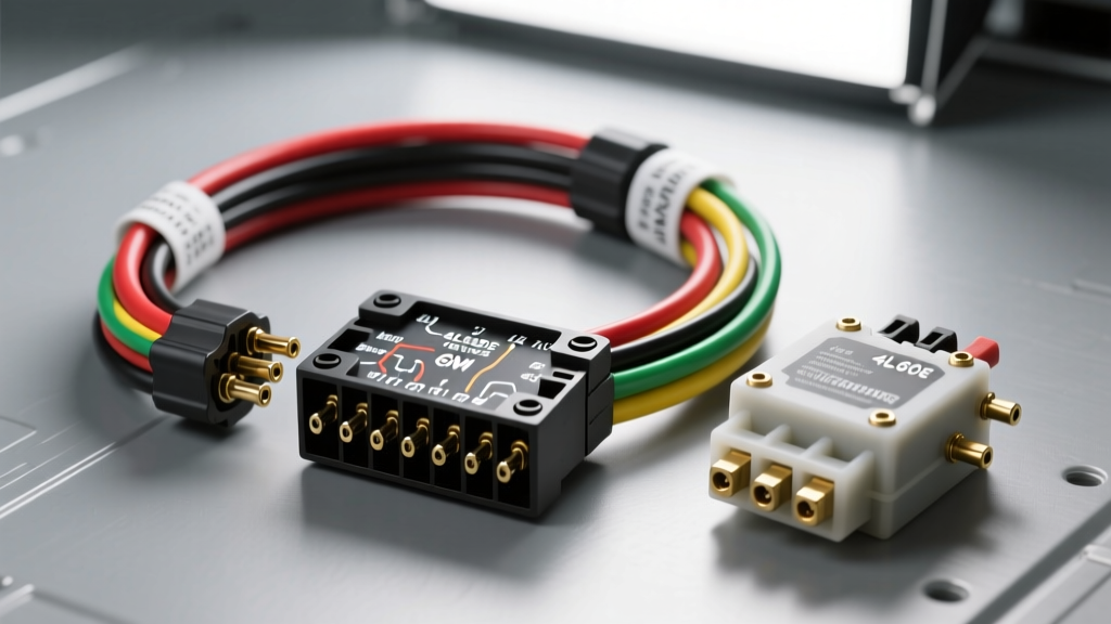
Understanding the 4L60E Neutral Safety Switch Circuit
The General Motors 4L60E transmission relies on a neutral safety switch (NSS) to prevent the engine from cranking while the transmission is in gear. In early 4L60E applications (1993-1995) and modern custom engine swap harnesses, this is accomplished via an external, case-mounted switch actuated by the shift linkage rosette. When integrating an aftermarket wiring harness or replacing a degraded OEM pigtail, proper installation of the 4L60E neutral safety switch wiring harness is critical. A poorly executed install can result in a no-crank condition, melted connector pins, or worse, a vehicle that starts in gear.
This practical guide covers the physical alignment, Metri-Pack connector crimping, and Bosch-style relay integration required to safely route the starter solenoid trigger circuit through the 4L60E NSS.
Required Tools and Wiring Specifications
Automotive electrical environments demand high-vibration, high-temperature components. Standard PVC wire and generic butt connectors will fail under the transmission pan. According to the SAE J1128 Low Tension Cable Standard, under-hood and under-carriage wiring should utilize cross-linked insulation.
- Wire Type: TXL or GXL (Thin-wall cross-linked polyethylene) for superior heat and abrasion resistance.
- Wire Gauge: 16 AWG for the NSS signal/trigger loop; 10 AWG for the starter relay power and ground feeds.
- Connector: GM Metri-Pack 280 series weather-sealed connector (4-pin).
- Crimping Tool: Ratcheting open-barrel crimper specific to Metri-Pack 280 tang-style terminals.
- Hardware: M6x1.0 flange bolts (OEM replacement if threads are damaged).
- Testing Equipment: Digital Multimeter (DMM) capable of measuring millivolt drops.
GM 4L60E NSS Pigtail Pinout Reference
The external 4L60E neutral safety switch typically utilizes a 4-pin Metri-Pack 280 connector. Two pins handle the starter interrupt circuit (Park/Neutral), while the other two handle the reverse backup lamps. Below is the standard pinout configuration used in most LS/4L60E swap harnesses.
| Pin | Function | Standard Swap Wire Color | AWG | Circuit Destination |
|---|---|---|---|---|
| A | P/N In (Start Trigger) | Purple | 16 | Ignition Switch 'Start' Terminal |
| B | P/N Out (Relay Trigger) | Purple w/ White Stripe | 16 | Starter Relay Pin 86 |
| C | Reverse In (12V Source) | Pink | 16 | Fused 12V Ignition Source |
| D | Reverse Out (Lamp Feed) | Dark Green | 16 | Rear Backup Lamp Harness |
Step-by-Step Harness Installation
Phase 1: Physical Mounting and Alignment
The most common cause of NSS failure is not electrical, but mechanical. If the switch is not perfectly aligned with the transmission's internal manual valve detents, the electrical contacts will not close in Park or Neutral.
- Set Transmission to Neutral: Rotate the shift shaft on the driver side of the 4L60E to the Neutral detent (typically the second click from the full forward Park position).
- Align the Switch: The external NSS features a neutral alignment mark (a small scribed line or notch on the inner rotor) that must perfectly align with the corresponding mark on the outer switch housing.
- Mount the Switch: Slide the switch over the shift shaft flat. Install the two M6 flange bolts. Crucial: Torque these bolts to exactly 11 lb-ft (15 Nm). Overtightening will crack the brittle Bakelite housing, allowing moisture to infiltrate the internal copper wipers.
- Verify Mechanical Operation: With a DMM set to continuity, probe Pins A and B. Rotate the shift shaft through all gears. Continuity should only exist in Park and Neutral. Continuity in Reverse or Drive indicates a misaligned switch or a worn internal rosette.
Phase 2: Metri-Pack Crimping and Routing
Proper crimping ensures the weather seals function correctly. As noted in Painless Performance Tech Tips, moisture wicking through poorly crimped terminals is a leading cause of harness failure.
- Prep the Wire: Strip exactly 3/16" of insulation from the 16 AWG TXL wire. Do not nick the copper strands.
- Slide on the Seal Boot: The silicone weather seal must be slid onto the wire before crimping the terminal. Ensure the small diameter end of the seal faces the terminal barrel.
- Crimp the Terminal: Use a ratcheting Metri-Pack 280 crimper. The wire insulation crimp (outer wings) should grip the TXL jacket tightly, while the conductor crimp (inner wings) forms a gas-tight fold around the bare copper.
- Seat the Terminal: Push the crimped terminal into the 4-pin connector housing until the tang clicks. Push the silicone seal forward until it bottoms out inside the housing cavity, creating a watertight barrier.
- Routing: Route the harness away from the exhaust crossover pipe and secure it to the transmission bellhousing bracket using high-temp nylon cable ties. Leave a 2-inch service loop near the switch to prevent tension on the pins during engine torque roll.
Integrating a Bosch-Style Starter Relay
A critical mistake made by novice fabricators is routing the starter solenoid current directly through the 4L60E neutral safety switch. The starter solenoid on a GM V8 can draw an inrush current of 30 to 45 amps. The Metri-Pack 280 pins in the NSS are rated for a maximum continuous load of 20 amps. Running solenoid current directly through the switch will melt the connector housing and fuse the contacts.
You must use a standard 4-pin Bosch-style 30A relay to isolate the high-amperage starter circuit from the low-amperage NSS trigger circuit. Referencing the Holley EFI Wiring Guidelines, wire the relay as follows:
- Pin 86 (Trigger +): Connect to NSS Pin B (Purple/White wire). This receives the 12V start signal only when the transmission is in Park or Neutral.
- Pin 85 (Trigger -): Connect to a clean, bare-metal chassis ground using 16 AWG wire.
- Pin 30 (High Current In): Connect directly to the battery positive terminal via a 40A maxi-fuse using 10 AWG wire.
- Pin 87 (High Current Out): Connect to the 'S' (Start) terminal on the starter solenoid using 10 AWG wire.
This configuration ensures the NSS only carries the relay coil draw (approximately 0.15 amps), vastly extending the life of the switch and preventing voltage drop to the starter solenoid.
Real-World Troubleshooting and Failure Modes
If the vehicle experiences a no-crank condition or intermittent starting issues after installation, avoid immediately replacing the switch. Perform these diagnostic steps to isolate the fault in the 4L60E neutral safety switch wiring harness.
1. The Voltage Drop Test (Under Load)
Continuity tests do not reveal high-resistance faults caused by corroded pins or loose crimps. To properly test the NSS circuit:
- Set the DMM to DC Volts.
- Place the red probe on NSS Pin A (Ignition Start feed) and the black probe on NSS Pin B (Relay Trigger feed).
- Have an assistant turn the ignition key to the 'Start' position.
- Specification: The voltage drop across the switch should be less than 0.1V (100mV). A reading above 0.3V indicates internal contact corrosion or a failing crimp joint, requiring switch or pigtail replacement.
2. Shift Linkage Slack and Cable Stretch
If the vehicle only cranks when the shifter is pulled slightly back from the full Park detent, the issue is rarely the wiring harness. It is almost always mechanical cable stretch. The shift cable stretches over time, preventing the transmission shift shaft from fully reaching the Park detent, thus leaving the NSS contacts slightly open. Adjust the cable tension at the transmission bracket before condemning the electrical harness.
3. Heat-Soak Resistance Spikes
If the vehicle cranks fine when cold but fails to crank after reaching operating temperature, inspect the routing of the Purple/White trigger wire. If the harness is zip-tied to the exhaust manifold or too close to the transmission cooler lines, the heat-soak will increase the electrical resistance of the copper wire. This resistance drops the voltage reaching the starter relay coil below the 9V threshold required to pull the relay contacts closed. Reroute the harness and wrap it in reflective heat-barrier sleeving.