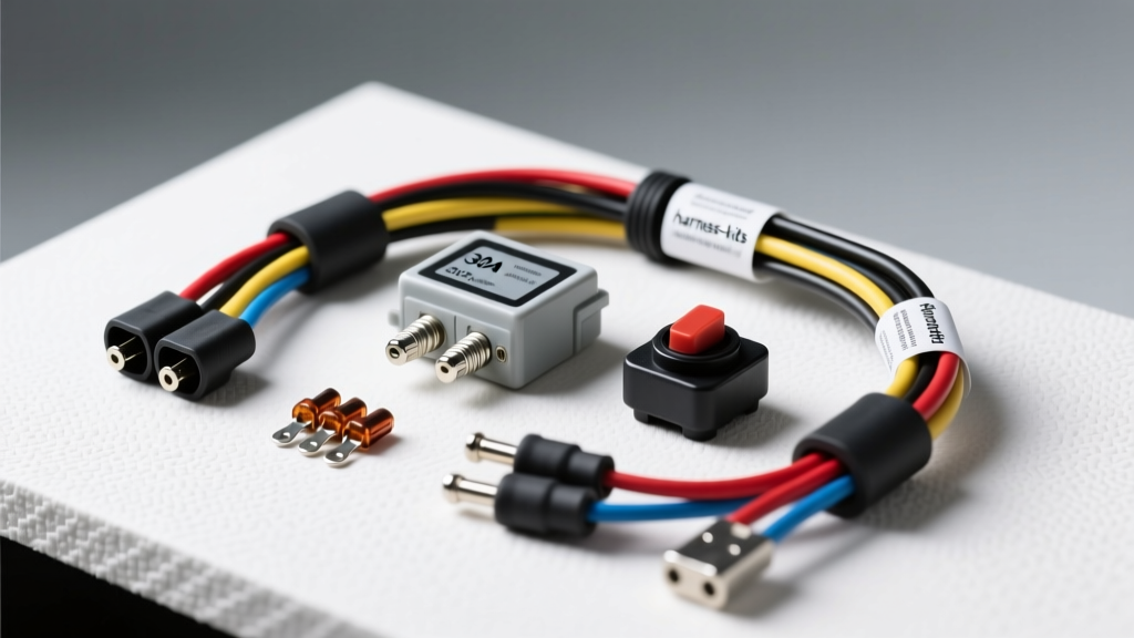
Introduction: The Necessity of a Dedicated Fog Lamp Wiring Harness
Upgrading your vehicle with auxiliary lighting is one of the most effective ways to improve nighttime visibility in adverse weather conditions. However, splicing high-draw fog lamps directly into your factory headlight circuit is a recipe for electrical failure. Modern vehicles utilize sensitive Body Control Modules (BCMs) and multiplexed CAN-bus systems that can trigger overcurrent faults or permanently damage OEM wiring if subjected to unregulated auxiliary loads. Installing a dedicated fog lamp wiring harness with an integrated relay and inline fuse bypasses the factory lighting circuit's current limitations, ensuring your OEM switches and modules remain protected while delivering maximum voltage to your new lamps.
Why Factory Headlight Switches Cannot Handle Fog Lamps
A standard pair of H11 55-watt fog lamps draws approximately 9.1 amps of continuous current (110W / 12.1V = 9.09A). While this may seem manageable, factory headlight switches and BCM solid-state relays are typically rated only for the specific OEM lighting load. Adding 9+ amps to an existing circuit causes excessive voltage drop and generates dangerous heat in factory 18 AWG or 20 AWG wires. By utilizing a heavy-duty fog lamp wiring harness, the high-current path runs directly from the battery to the lamps via a 30-amp automotive relay, while the dashboard switch only carries the minimal milliamp trigger current required to activate the relay coil.
Required Tools and Harness Specifications
Before beginning the installation, ensure your harness kit and tools meet automotive-grade standards. According to SAE J1128 standards, under-hood wiring must utilize cross-linked polyethylene insulation (GXL or TXL) to withstand 125°C ambient temperatures and resist abrasion.
| Component | Specification | Purpose |
|---|---|---|
| Primary Power Wire | 12 AWG GXL (Red) | Handles up to 20A; minimizes voltage drop over long engine bay runs. |
| Relay Ground Wire | 12 AWG GXL (Black) | Provides low-resistance path to chassis ground. |
| Switch Trigger Wire | 18 AWG TXL (Yellow/White) | Carries low-current signal from dash switch to relay coil. |
| Inline Fuse Holder | ATC/ATO with 15A Blade Fuse | Protects 12 AWG harness from dead shorts (125% of 9.1A load). |
| Automotive Relay | 12V 30/40A SPST (Bosch-style) | Switches high current via low-current trigger. |
| Connectors | H11/H8 Waterproof Pigtails | Prevents moisture ingress and corrosion at the bulb housing. |
Step-by-Step Fog Lamp Wiring Harness Installation
Step 1: Battery Disconnect and Relay Mounting
Always disconnect the negative battery terminal before working on any automotive electrical system to prevent accidental shorts. Locate a suitable mounting point for the 30A relay. The relay must be mounted in an upright position (pins facing down) to prevent water from pooling in the connector cavity. Choose a location on the inner fender well or radiator support that is shielded from direct exhaust heat and road debris. Secure the relay bracket using self-tapping stainless steel screws and apply a dab of dielectric grease to the relay terminals before plugging in the harness socket.
Step 2: Routing the Power and Ground Circuits
Route the 12 AWG red power wire from the positive battery terminal to the relay location. Crucial: Install the ATC inline fuse holder within 6 inches of the battery terminal connection. This ensures the entire length of the wire is protected in the event of a short to the chassis. Use split-loom tubing or Tesa cloth tape to protect the wire from sharp metal edges and moving components like cooling fans or accessory belts. For the 12 AWG black ground wire, locate a bare, unpainted metal surface on the chassis. Remove any powder coating or rust, secure the ring terminal with a star washer to ensure a gas-tight connection, and coat the terminal with silicone sealant to prevent galvanic corrosion.
Step 3: Wiring the Relay Control Circuit
The relay control circuit utilizes 18 AWG wire. You will need to source a switched 12V+ signal from the cabin to trigger the relay. This can be tapped from an auxiliary switch panel, a blank OEM fog light switch on the steering column, or an add-a-circuit fuse tap connected to an ignition-switched fuse (e.g., windshield wipers or radio). Route the 18 AWG trigger wire through an existing rubber firewall grommet—never pierce a grommet directly, as this compromises the cabin's weather seal. Connect this trigger wire to Pin 86 on the relay. Connect the Pin 85 wire to a clean chassis ground.
Step 4: Connecting the Fog Lamps and Dashboard Switch
Route the 12 AWG blue (or white) output wire from Pin 87 of the relay down to the front bumper where the fog lamps are mounted. Split the wire using a sealed, heat-shrink butt connector or a weather-pack distribution block to feed both lamps. Plug the H11 waterproof pigtails into the fog lamp housings. Ground the secondary side of the fog lamps to the bumper support beam. Finally, reconnect the battery and test the circuit. As outlined in AutoShop101 Electrical Fundamentals, verifying voltage at the lamp connector with a digital multimeter (DMM) under load is the best way to confirm a successful installation. You should read no less than 11.8V at the lamp connector with the engine running.
Standard 4-Pin Automotive Relay Pinout Reference
Understanding the DIN 72552 standard relay pinout is critical for correctly wiring your fog lamp harness. Miswiring the control and load circuits will result in blown fuses or a continuously running lamp.
| Pin Number | Circuit Type | Connection Target | Wire Color (Standard) |
|---|---|---|---|
| 30 | Common (Input) | Direct 12V+ from Battery (via 15A Fuse) | Red (12 AWG) |
| 87 | Normally Open (Output) | Positive Input to Fog Lamps | Blue (12 AWG) |
| 86 | Coil Trigger (Input) | Switched 12V+ from Dash Switch | Yellow/White (18 AWG) |
| 85 | Coil Ground (Output) | Chassis Ground | Black (18 AWG) |
Troubleshooting Common Harness Failure Modes
Even with a premium fog lamp wiring harness, installation errors can occur. Use the following decision tree to diagnose common issues. For deeper diagnostic procedures, refer to Hella Lighting Technical Guides on auxiliary lamp integration.
| Symptom | Probable Cause | Diagnostic Fix |
|---|---|---|
| Relay clicks, but lamps do not illuminate. | Loss of power on Pin 30 or open circuit on Pin 87. | Check 15A inline fuse. Test Pin 30 for 12V+. Check for broken 12 AWG wire to lamps. |
| Lamps illuminate but are noticeably dim. | Excessive voltage drop due to poor ground or undersized wire. | Measure voltage at lamp connector under load. Clean chassis ground; ensure star washer bites into bare metal. |
| Relay does not click when dash switch is activated. | Missing trigger voltage on Pin 86 or open ground on Pin 85. | Test Pin 86 for 12V+ when switch is ON. Verify Pin 85 has continuity to chassis ground. |
| Lamps turn on immediately upon battery connection, bypassing switch. | Relay wired backwards or internally shorted. | Verify Pin 30 and Pin 87 are not swapped. Test relay on a bench with a 12V power supply. |
| Fuse blows instantly when switch is flipped. | Dead short to ground on Pin 87 output wire. | Inspect 12 AWG output wire for pinched insulation against sharp bumper brackets or radiator supports. |
Pro-Tip: Crimping vs. Soldering in Automotive Harnesses
When terminating your fog lamp wiring harness to ring terminals or bullet connectors, always use a high-quality ratcheting crimper rather than solder. Under-hood environments subject wiring to extreme thermal cycling and high-frequency vibrations. Soldered joints can become brittle and fracture under these conditions, leading to intermittent arcing. A properly executed mechanical crimp creates a cold-weld gas-tight seal that maintains structural integrity and conductivity far longer than solder in automotive applications. Finish the connection with adhesive-lined, dual-wall heat shrink to completely seal out moisture and road salt.