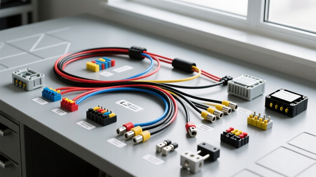
Introduction to Gen III/IV LS Wiring Harness Architecture
Swapping a General Motors Gen III or Gen IV LS engine into a classic chassis or non-native platform requires more than just motor mounts and a transmission crossmember; it demands a rigorous understanding of the electrical architecture. These comprehensive LS wiring harness instructions provide a complete diagram walkthrough for the factory-style Powertrain Control Module (PCM) harness. Whether you are retaining the factory harness, modifying a standalone kit, or building a custom loom from bare wire, understanding the baseline General Motors circuit topology is critical for a reliable, drivable swap.
The factory LS1/LS6 (Gen III) harness relies on a speed-density or MAF-based tuning strategy, utilizing a complex network of 5-volt reference circuits, low-current signal returns, and high-current switched grounds. Modifying these circuits without adhering to SAE J1128 standards for primary automotive cable can lead to voltage drop, sensor failure, and catastrophic PCM damage.
Decoding the Main PCM Connectors (C1 and C2)
The Gen III LS PCM utilizes two primary 80-way connectors: C1 (Blue lever) and C2 (Red lever). Later Gen IV platforms introduced a third connector (C3 - Black), but the foundational power, ground, and injector circuits remain remarkably consistent across the LS swap ecosystem. When following your LS wiring harness instructions, identifying the primary ignition and battery feeds is step one.
Critical Power and Ground Distribution
The PCM requires clean, unswitched battery voltage for Keep Alive Memory (KAM) and switched ignition voltage to wake up the internal drivers. Below is the definitive pinout table for the main power and ground circuits on the C1 (Blue) connector.
| Connector | Pin Number | Wire Color | AWG Size | Circuit Function | Source / Destination |
|---|---|---|---|---|---|
| C1 (Blue) | 20 | Orange | 14 AWG | Battery 12V+ (Constant) | Main Fuse Box / Battery |
| C1 (Blue) | 19 | Pink | 14 AWG | Ignition 12V+ (Switched) | Ignition Switch Run/Start |
| C1 (Blue) | 21 | Black/White | 14 AWG | PCM Logic Ground | Engine Block / Chassis |
| C1 (Blue) | 59 | Black/White | 14 AWG | PCM Logic Ground | Engine Block / Chassis |
| C2 (Red) | 79 | Black | 14 AWG | PCM Power Ground (Injectors) | Engine Block / Chassis |
Expert Note: Never route PCM ground wires to painted sheet metal or the intake manifold. All grounds must terminate at a dedicated, bare-metal stud on the engine block or cylinder head to prevent ground loop interference, which frequently manifests as erratic idle or random misfire codes (P0300).
Walkthrough: Injector and Coil Pack Wiring
The LS platform utilizes sequential port fuel injection and individual coil-near-plug (CNP) ignition. Unlike older batch-fire systems, the PCM fires each injector and coil individually based on precise crankshaft position data.
Injector Circuit Topology
Each fuel injector receives constant 12V+ from a fused ignition source (typically a 15A fuse per bank). The PCM controls the injector by pulsing the ground path. The injector power feed wires are universally Pink (14 AWG). The PCM ground control wires vary by cylinder:
- Bank 1 (Cylinders 1, 3, 5, 7): C1 Connector Pins 76, 75, 74, 73. Wire colors: Brown, Brown/White, Dark Blue, Dark Blue/White.
- Bank 2 (Cylinders 2, 4, 6, 8): C2 Connector Pins 58, 57, 56, 55. Wire colors: Dark Green, Dark Green/White, Purple, Purple/White.
When modifying harness lengths, ensure all injector wires are kept under 120 inches total to maintain the factory RC time constant. If extending, use 14 AWG TXL (Cross-linked polyethylene) wire to match factory impedance and prevent voltage drop across the circuit.
Fuel Pump Relay Configuration and Wire Gauges
A frequent failure point in DIY LS swaps is the fuel pump relay wiring. The PCM does not power the fuel pump directly; it triggers a standard ISO mini relay. Pin 22 on the C1 connector (Dark Green wire, 18 AWG) provides the ground trigger for the fuel pump relay coil.
Standard ISO Relay Pinout for LS Fuel Pumps
When integrating an aftermarket fuel pump module (such as a Walbro 255 or Aeromotive 340), wire the relay according to this diagram standard:
- Pin 30 (12V BATT Feed): 10 AWG Red wire directly from the battery with a 20A inline fuse.
- Pin 87 (Normally Open Output): 10 AWG Grey wire to the fuel pump positive terminal.
- Pin 86 (Coil 12V+): 14 AWG Pink wire from a switched ignition source.
- Pin 85 (Coil Ground Trigger): 18 AWG Dark Green wire to PCM C1 Pin 22.
Troubleshooting Tip: If your fuel pump primes for exactly 2 seconds and then shuts off permanently while cranking, verify the connection at C1 Pin 22. If the PCM loses its primary ground during cranking voltage drop, it will reset and cut the fuel pump relay trigger.
Sensor Integration: TPS, MAP, and IAT Wiring
The 5-volt reference (5VREF) circuit is the backbone of the LS sensor network. The PCM generates a highly regulated 5V signal shared by the Throttle Position Sensor (TPS), Manifold Absolute Pressure (MAP) sensor, and Accelerator Pedal Position (APP) sensor (if using Drive-by-Wire).
Throttle Position Sensor (TPS) Pinout
For cable-throttle LS1/LS6 applications, the TPS is a 3-wire potentiometer:
- 5V Reference: Grey wire (PCM C1 Pin 33). Must read exactly 4.95V to 5.05V with Key-On-Engine-Off (KOEO).
- Low Reference (Ground): Black wire (PCM C1 Pin 34). This is a dedicated PCM sensor ground, not a chassis ground.
- Signal Return: Dark Blue wire (PCM C1 Pin 32). Sweeps from ~0.5V (closed throttle) to ~4.5V (WOT).
Never splice into the 5V reference wire to power aftermarket gauges or secondary sensors. Drawing even 50 milliamps from this shared circuit will pull the voltage down to 4.8V, causing the PCM to set a P0122 (TPS Circuit Low) code and trigger limp-home mode. For detailed factory diagnostic trees and sensor voltage parameters, refer to the GM Factory Service Manuals published by Helm Incorporated.
Troubleshooting Common LS Swap Harness Faults
When following aftermarket LS swap harness instructions, technicians frequently encounter specific electrical gremlins. Use this decision tree to diagnose common swap-related harness faults:
- Symptom: Engine cranks but no injector pulse or spark.
- Cause: Missing Crankshaft Position Sensor (CKP) signal.
- Fix: Check CKP wiring (C2 Pin 66 and 67). Ensure the sensor is fully seated against the block and the reluctor wheel on the crank is not damaged.
- Symptom: Random P0300 misfire codes at high RPM.
- Cause: Voltage drop on the coil pack 12V+ feed.
- Fix: The factory harness uses 14 AWG Pink wires for coil power. If you extended these with undersized 18 AWG wire, voltage drops below 10V under load. Upgrade all coil feeds to 12 AWG TXL wire.
- Symptom: Alternator not charging / Battery light stays on.
- Cause: Missing 'L' terminal exciter wire.
- Fix: LS alternators require a 12V+ pulse to the 'L' pin on the 4-way connector to 'wake up' the internal regulator. Wire the Red (Pin D) terminal to a switched 12V source via a 194 bulb or 500-ohm resistor.
Final Grounding and Shielding Protocols
The ultimate success of your LS swap relies on the integrity of your grounding strategy. The factory LS harness utilizes a heavy 1/0 AWG ground strap connecting the passenger side cylinder head to the chassis. In a swap vehicle, you must replicate this. Run a dedicated 1/0 AWG flexible copper strap from the rear of the passenger cylinder head directly to the vehicle's main battery negative terminal or a dedicated chassis ground bus bar. Furthermore, ensure that the oxygen sensor harnesses are routed at least 4 inches away from spark plug wires and exhaust headers to prevent electromagnetic interference (EMI) and thermal degradation of the sensor signal wires.