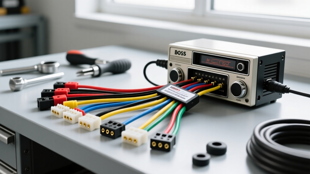
The Anatomy of a Boss Audio Head Unit Upgrade
Swapping a failing factory stereo or upgrading to a modern infotainment system is one of the most impactful modification projects you can tackle. When installing an aftermarket head unit from Boss Audio Systems, the critical bridge between your vehicle's complex electrical network and the new stereo is the Boss radio wiring harness. While Boss units are renowned for their budget-friendly feature sets, integrating them into modern vehicles requires a meticulous approach to wiring. Splicing directly into factory wires is a relic of the past; today's CAN-bus networks, multiplexed data lines, and factory amplifiers demand precise harness adapters and strict adherence to automotive electrical standards.
In this comprehensive upgrade guide, we will dissect the universal Boss radio wiring harness pinout, explore vehicle-specific adapter integration, and detail the exact wire gauges and crimping methodologies required to ensure a reliable, noise-free installation that preserves your vehicle's battery life and steering wheel controls.
Universal Boss Radio Wiring Harness Pinout Chart
Most standard single-DIN and double-DIN Boss Audio head units utilize a standardized 16-pin or 20-pin proprietary connector that breaks out into an 18 AWG stranded copper pigtail. These wire colors follow the Consumer Technology Association (CTA) mobile electronics standards, ensuring compatibility with almost all aftermarket adapter harnesses.
| Wire Color | Function | Standard AWG | Technical Notes & Integration Tips |
|---|---|---|---|
| Yellow | 12V Constant (Memory) | 18 AWG | Connects to a fused always-on 12V source. Maintains radio presets and EQ settings. Do not swap with Red. |
| Red | 12V Switched (Ignition) | 18 AWG | Triggers the head unit ON/OFF. Must be tied to an ignition-controlled circuit to prevent parasitic battery drain. |
| Black | Chassis Ground | 18 AWG | Must be terminated to a clean, unpainted metal surface or tied to the adapter harness ground. Never use the cigarette lighter ground. |
| Blue | Power Antenna Trigger | 18 AWG | Outputs +12V only when the AM/FM tuner is active. Used for motorized mast antennas. |
| Blue/White Stripe | Amplifier Turn-On | 18 AWG | Outputs +12V whenever the unit is powered on. Connect to the remote turn-on lead of external amps or DSPs. |
| White / White-Black | Front Left Speaker (+/-) | 18 AWG | Ensure proper phase alignment. Black tracer indicates negative. |
| Gray / Gray-Black | Front Right Speaker (+/-) | 18 AWG | Verify with a 9V battery pop-test if factory adapter colors are ambiguous. |
| Green / Green-Black | Rear Left Speaker (+/-) | 18 AWG | If using a factory amplified system, these must interface with a line-out converter (LOC) or bypass the factory amp. |
| Purple / Purple-Black | Rear Right Speaker (+/-) | 18 AWG | Keep speaker wires isolated from RCA patch cables to prevent crosstalk and alternator whine. |
| Orange/Illumination | Dashboard Dimmer | 20 AWG | Often omitted in modern Boss units, but if present, connects to the headlight switch dimmer circuit. |
Vehicle-Specific Adapter Harnesses: The Golden Rule of Modding
The golden rule of any automotive audio modification is never cut the factory harness. To integrate your Boss radio wiring harness with the vehicle, you must use a vehicle-specific T-harness or ISO adapter (manufactured by brands like Metra, Axxess, or Scosche). These adapters plug directly into the OEM radio plug and feature a color-coded pigtail that matches the Boss universal colors outlined above.
Retaining Steering Wheel Controls (SWC) and CAN-Bus
In vehicles manufactured after 2008, the factory radio is often a module on the Controller Area Network (CAN-bus). The ignition switch does not send a physical 12V switched signal to the radio; instead, it sends a digital wake-up command over the CAN-High and CAN-Low twisted pair wires. If you attempt to wire a standard Boss harness directly into a CAN-bus vehicle without a data retention module, the radio will not turn on, or worse, it will remain on and drain the battery because it never receives the digital 'sleep' command.
For these modification projects, you must use a CAN-bus interface module (such as the Axxess ASWC-1 or iDatalink Maestro). The interface module intercepts the vehicle's data network, translates the digital CAN-bus commands, and outputs a physical 12V switched signal to the Red wire on your Boss radio wiring harness, while simultaneously retaining steering wheel volume and track controls.
Advanced Power Upgrades: Bypassing the 18 AWG Bottleneck
While the standard Boss radio wiring harness utilizes 18 AWG wire, this gauge is only rated for approximately 14 amps of continuous current over short runs, per the SAE J1128 Low Tension Primary Cable Standard. If you are installing a high-powered Boss head unit with a built-in 4x50W MOSFET amplifier and pushing the volume to maximum, the 18 AWG power and ground wires can experience voltage drop, leading to clipping, distorted audio, and head unit reboots.
The Expert Fix: For high-draw modification projects, cut the 18 AWG Yellow and Black wires near the Boss harness plug. Splice in 12 AWG or 14 AWG primary automotive wire for the constant 12V and ground connections. Run the 12 AWG Yellow wire directly to the vehicle's battery (with an inline 15A ATC fuse located within 18 inches of the battery terminal) and terminate the 12 AWG Black wire to a heavy-gauge chassis bolt in the cabin. This ensures maximum current delivery and eliminates ground-loop induced alternator whine.
Step-by-Step Harness Fabrication and Connection
Proper termination is what separates a professional installation from a fire hazard. Do not use electrical tape or cheap twist-on connectors. Follow this procedure for joining the Boss radio wiring harness to your vehicle adapter:
- Prep the Wires: Strip exactly 5/16 inch of insulation from both the Boss harness and the adapter harness wires using a precision wire stripper to avoid nicking the copper strands.
- Select Connectors: Use marine-grade, adhesive-lined solder-seal heat shrink butt connectors. These provide a waterproof, vibration-proof seal that meets CTA Mobile Electronics Standards for harsh automotive environments.
- Crimp and Heat: Crimp the connector barrels using a ratcheting crimping tool. Apply heat with a heat gun (not a lighter) until the adhesive melts and flows out of the ends of the shrink tubing.
- Verify with a DMM: Before plugging the harness into the Boss head unit, use a Digital Multimeter (DMM) to verify that the adapter's Yellow wire shows 12.2V-12.6V constant, and the Red wire shows 0V with the key off, and 12.2V+ with the key in the 'ACC' or 'ON' position.
- Secure the Loom: Wrap the completed harness junction in Tesa cloth friction tape to prevent rattling behind the dashboard, and use a zip-tie to secure the slack to a factory dashboard support bracket.
Troubleshooting Common Boss Harness Integration Faults
Parasitic Draw and Battery Drain
Symptom: Vehicle battery is dead after sitting for 24 hours. Cause: The Yellow (Constant) and Red (Switched) wires on the Boss harness were swapped at the adapter, or the CAN-bus interface module is failing to send the sleep command. Fix: Test with a DMM. If the radio retains memory but the ignition key does not turn the unit off, swap the Red and Yellow connections at the harness junction. If the unit turns off but the vehicle CAN-bus stays awake, verify the interface module's ground and data-line pinouts using the Metra Electronics Vehicle Fitment Database.
Alternator Whine and Ground Loops
Symptom: A high-pitched whining noise through the speakers that increases in pitch with engine RPM. Cause: The head unit ground and the external amplifier ground are at different electrical potentials, or the 18 AWG Boss ground wire is sharing a return path with noisy factory modules. Fix: Isolate the Boss radio ground. Run a dedicated 14 AWG ground wire from the back of the head unit directly to the vehicle's main chassis ground point or the negative battery terminal. Ensure all RCA cables are routed on the opposite side of the vehicle from the power cables.
Marine and Motorsport Boss Harness Variations
If your modification project involves a boat, UTV, or motorcycle, standard 18 AWG pigtails will fail rapidly due to UV exposure and moisture intrusion. Boss Audio marine and motorsport head units utilize sealed Weather-Pack or Deutsch DT connectors. When fabricating extension harnesses for these applications, you must use 16 AWG cross-linked polyethylene (XLPE) jacketed wire and crimp the terminals using a specialized open-barrel crimping tool (such as the IWISS SN-28B) to ensure the silicone cavity plugs seal perfectly against the wire jacket.