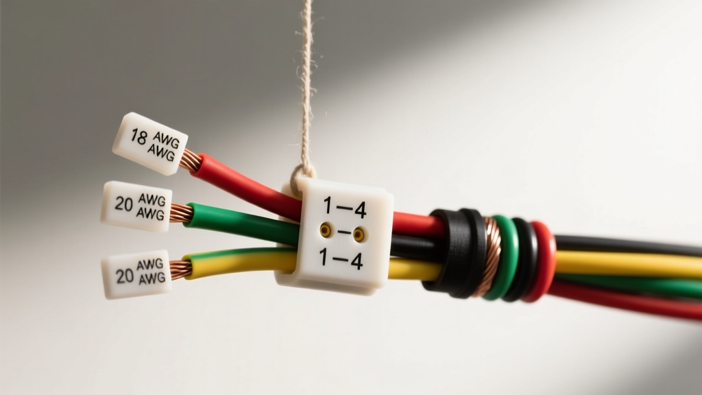
Introduction to Heated O2 Sensor Harness Architecture
The oxygen sensor is the primary feedback mechanism for closed-loop fuel control in modern internal combustion engines. However, the sensor itself is only as reliable as the O2 sensor wiring harness that connects it to the Powertrain Control Module (PCM). Operating in one of the most hostile environments of any vehicle electrical system, the O2 sensor wiring harness must withstand extreme radiant heat from the exhaust manifold, severe vibration, and exposure to corrosive road salts and exhaust condensate.
When fabricating a custom engine swap harness, repairing a melted pigtail, or designing an OEM-replacement harness kit, adhering to strict electrical specifications is non-negotiable. A marginal voltage drop on the signal ground or an undersized heater circuit wire will immediately trigger Diagnostic Trouble Codes (DTCs) such as P0131 (O2 Sensor Circuit Low Voltage) or P0031 (HO2S Heater Control Circuit Low). This technical reference outlines the exact pinouts, wire gauge requirements, and material specifications required for narrowband and wideband O2 sensor harnesses.
4-Wire Narrowband O2 Sensor Pinout & Color Code Matrix
The 4-wire heated narrowband zirconia sensor remains the most common architecture in legacy and modern V8 engine swaps (such as GM LS and Ford Coyote platforms). The harness is divided into two distinct, isolated circuits: the high-impedance signal circuit and the high-current heater circuit.
| Pin | Circuit Function | GM LS Gen III/IV Color | Ford Coyote Color | Min AWG | Expected Voltage |
|---|---|---|---|---|---|
| A | O2 Signal (High) | Purple | White/Red | 22 AWG | 0.1V - 0.9V (Oscillating) |
| B | O2 Signal Ground (Low) | Tan | White/Yellow | 22 AWG | ~0.0V (Dedicated PCM Ground) |
| C | Heater Power (12V+) | Pink | Red/White | 14 AWG | 12V - 14.5V (Ignition/Relay) |
| D | Heater Ground (PWM) | Black/White Stripe | Black/White | 14 AWG | PCM Modulated Ground |
Note: Never splice the O2 Signal Ground into the engine block or chassis ground. It must be a dedicated, isolated ground routed directly back to the PCM to prevent ground loop interference from the alternator or ignition system.
Signal Circuit Specifications
The signal circuit operates on a high-impedance principle. The PCM provides a bias voltage (typically 0.45V), and the zirconia element generates a millivolt-level response based on the oxygen differential between the exhaust gas and ambient air. Because the current flow is measured in microamps, the harness must utilize a minimum of 20 to 22 AWG wire. More importantly, the insulation material must possess high dielectric strength. Cross-linked polyethylene (XLPE) or Tefzel (ETFE) insulation is required to prevent signal leakage when the harness is exposed to underhood moisture.
For custom harness fabrication, the signal pair (Signal and Signal Ground) should be twisted at a rate of 4 to 6 twists per foot to reject Electromagnetic Interference (EMI) generated by high-energy ignition coils and fuel injector drivers.
Heater Circuit Specifications
The internal ceramic heater element requires substantial current to reach its operational threshold of 600°F (315°C) within seconds of a cold start. According to Bosch Mobility Solutions technical data, initial inrush current for a standard 4-wire sensor can peak between 8 and 12 Amps before the PCM's Pulse Width Modulation (PWM) driver throttles it to a steady state of 2 to 4 Amps.
Using 18 AWG wire for the heater circuit—a common mistake in amateur engine swap harnesses—will result in excessive resistance. A resistance increase of just 0.5 ohms across the heater ground wire will cause a voltage drop that the PCM interprets as a failed heater element, setting DTC P0031 or P0051. Always use 14 AWG stranded copper for heater power and ground circuits, rated for a minimum of 105°C.
Wideband (AFR) Harness Architecture: The 5-Wire and 6-Wire Standard
When tuning high-performance or forced-induction applications, a wideband Air/Fuel Ratio (AFR) sensor is mandatory. The industry standard Bosch LSU 4.9 wideband sensor requires a more complex O2 sensor wiring harness due to its dual-cell design (Nernst voltage cell and oxygen pump cell).
Bosch LSU 4.9 Pinout Reference
- Pin 1 (White): Heater Power (HTR+) - 14 AWG
- Pin 2 (Yellow): Heater Ground (HTR-) - 14 AWG
- Pin 3 (Red): Pump Cell High (IP+) - 20 AWG
- Pin 4 (Blue): Pump Cell Low (IP-) - 20 AWG
- Pin 5 (Black): Nernst Signal (VS+) - 20 AWG
- Pin 6 (Grey): Calibration / Trim Resistor - 22 AWG
The wideband harness requires strict adherence to wire length matching. The calibration resistor located in the connector shell is laser-trimmed at the factory to compensate for the specific sensor's manufacturing tolerances. If you must extend a wideband O2 sensor wiring harness, all six wires must be extended by the exact same length using identical AWG and material to maintain the calibration resistance and prevent skewed AFR readings.
Connector Types and Terminal Retention Specs
The physical connection at the sensor is just as critical as the wire gauge. The automotive industry standard for O2 sensor connections is the Delphi (Aptiv) Metri-Pack 280 series or the Bosch EV1/EV6 style molded connector.
When assembling a replacement harness kit, you must use high-temperature thermoplastic shells, typically PA66 GF30 (Polyamide 66 with 30% Glass Fiber), which can withstand continuous operating temperatures of 150°C. Standard PVC connectors will become brittle and shatter under exhaust heat cycles.
Terminal retention is vital. The Metri-Pack 280 female terminals utilize a primary and secondary lock mechanism (TPA - Terminal Position Assurance). When crimping, use a calibrated ratcheting crimp tool specific to Metri-Pack 280 terminals to achieve the required pull-out force specification of >40 Newtons. A loose terminal will cause micro-arcing, rapidly oxidizing the contact surface and introducing resistance into the signal circuit.
Common Harness Failure Modes & Diagnostic Voltage Drops
When diagnosing O2 sensor faults, technicians often replace the sensor when the actual failure lies within the harness. Refer to the AutoShop 101 Automotive Electrical Circuits guide for foundational voltage drop testing methodologies. Below are the most common O2 sensor wiring harness failure modes:
1. The Drip Loop Omission (Galvanic Corrosion)
Symptom: Intermittent lean codes (P0171/P0174) that only occur during high-humidity or rainy conditions.
Cause: The harness was routed directly from the sensor to the PCM without a drip loop. Condensation forms on the sensor body, wicks down the wire via capillary action, and pools inside the Metri-Pack connector, causing a short between the signal and ground pins.
Fix: Always route the harness downward from the sensor, creating a 'U' shaped drip loop below the connector before securing it to the chassis or transmission bellhousing.
2. Heater Ground Chafing
Symptom: Blown O2 heater fuse or PCM driver failure.
Cause: The 14 AWG heater ground wire is zip-tied too tightly to the exhaust manifold or engine block. Engine torque roll causes the wire to chafe against a sharp bracket, shorting the PWM ground directly to the chassis before it reaches the PCM.
Fix: Use high-temperature fiberglass or silicone sleeving (rated to 260°C / 500°F) over the first 12 inches of the harness nearest the sensor. Secure the harness using stainless steel cushion clamps (P-clips) with high-temp silicone liners, maintaining a minimum 2-inch clearance from all exhaust components.
3. Signal Wire Shielding Breach
Symptom: Erratic O2 voltage readings on a datalogger, jumping from 0.1V to 0.9V rapidly without corresponding fuel trims changes.
Cause: The O2 signal wire was routed parallel to a high-current circuit, such as an electric cooling fan relay feed or an ignition coil power wire, inducing an alternating current (AC) noise onto the direct current (DC) signal line.
Fix: If the signal wire must cross a high-current harness, it must do so at a strict 90-degree angle. Never run O2 signal wires in the same split-loom conduit as injector or ignition harnesses.
Wire Insulation Material Selection
According to the SAE J1128 Low Tension Primary Cable Standard, wire insulation must be selected based on the specific temperature zone of the engine bay. For O2 sensor wiring harnesses, standard PVC (SXL/GXL) is insufficient for the section of the harness exposed to radiant exhaust heat. Fabricators must transition to Cross-Linked ETFE (Tefzel) or Silicone-coated Fiberglass for the pigtail and the first 18 inches of the harness run. Tefzel wire offers superior resistance to heat, chemicals, and abrasion, and its thin-wall construction allows for tighter bend radii in confined transmission tunnel and exhaust header clearances.