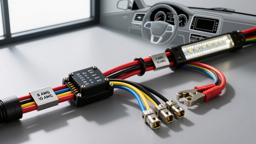
Engineering a High-Amperage LED Light Bar Wiring Harness
Integrating auxiliary lighting arrays exceeding 300W into modern vehicle electrical systems requires far more than a generic plug-and-play kit. A 300W LED light bar operating on a 14.4V charging system draws approximately 20.8 amps continuously. When scaling up to 600W or 1000W arrays, current demands surge to 41A and 69A respectively. Standard 14 AWG wiring and 30A automotive relays found in off-the-shelf kits will rapidly succumb to thermal degradation, voltage drop, and contact welding under these loads. This advanced technical deep dive explores the electrical engineering principles required to fabricate a robust, failure-resistant LED light bar wiring harness, adhering to strict SAE standards for voltage drop, thermal management, and electromagnetic compatibility.
Calculating AWG and Voltage Drop for High-Wattage Arrays
The most common point of failure in aftermarket auxiliary lighting is excessive voltage drop across the primary power and ground circuits. According to SAE J1113 and general automotive electrical best practices, a maximum voltage drop of 3% (0.42V on a 14.0V system) is acceptable for critical lighting circuits. Exceeding this threshold drastically reduces LED lumen output, shifts color temperature, and forces the internal constant-current drivers to draw higher amperage to compensate, accelerating thermal failure.
The Voltage Drop Formula
To calculate the required American Wire Gauge (AWG) for your harness, utilize the standard DC voltage drop formula:
V_d = 2 × L × I × R
- V_d: Voltage Drop (Target ≤ 0.42V)
- L: One-way length of the wire in feet
- I: Current draw in Amperes
- R: Resistance per foot of the specific AWG wire (e.g., 10 AWG copper = 0.001018 Ω/ft)
AWG Sizing Chart for 3% Maximum Voltage Drop (14.0V System)
| Target Load (Watts) | Current Draw @ 14.0V | Recommended AWG | Max One-Way Run (Ft) | Max One-Way Run (Meters) |
|---|---|---|---|---|
| 150W - 200W | 10.7A - 14.2A | 12 AWG (GXL) | 12 Feet | 3.6 Meters |
| 300W - 400W | 21.4A - 28.5A | 10 AWG (SGX) | 14 Feet | 4.2 Meters |
| 500W - 600W | 35.7A - 42.8A | 8 AWG (SGX) | 12 Feet | 3.6 Meters |
| 800W - 1000W | 57.1A - 71.4A | 6 AWG or 4 AWG | 10 Feet (6 AWG) | 3.0 Meters (6 AWG) |
For harness fabrication, always specify SXL, GXL, or TXL cross-linked polyethylene (XLPE) insulated wire rather than standard PVC. GXL wire features a 125°C temperature rating and a thinner insulation wall, allowing for tighter bend radii in engine bays while resisting under-hood heat soak.
ISO Relay Architecture and Inductive Spike Protection
Direct switching of high-amperage lighting loads via a dashboard toggle switch is a fire hazard. The harness must utilize an ISO 7588-1 Mini Relay (commonly referred to as a Bosch-style relay) to isolate the high-current load circuit from the low-current trigger circuit. For loads exceeding 40A, standard 40A ISO relays will experience contact arcing and eventual welding. In these scenarios, utilize a high-current ISO Maxi relay or a solid-state contactor rated for 70A+ continuous duty.
Standard ISO Mini Relay Pin Configuration
| Pin Number | Terminal Designation | Function & Wire Color Code | Wire Gauge (AWG) |
|---|---|---|---|
| 30 | Common (Input) | Main Battery Power (Red) | Match Load AWG |
| 87 | Normally Open (Output) | Load Power to Light Bar (Blue/White) | Match Load AWG |
| 85 | Coil Ground | Relay Coil Ground (Black) | 16 AWG |
| 86 | Coil Trigger | Switch/BCM Trigger (Yellow) | 16 AWG |
| 87a | Normally Closed | Not Used in Lighting (Cut/Seal) | N/A |
Critical Protection: The Flyback Diode
When tapping into modern Body Control Modules (BCMs) or solid-state ignition circuits for the relay trigger (Pin 86), you must protect the vehicle's sensitive silicon from inductive kickback. When the relay coil is de-energized, the collapsing magnetic field generates a reverse voltage spike that can exceed 100V, instantly destroying a BCM transistor. To prevent this, solder a 1N4001 or 1N4004 rectifier diode across Pins 85 and 86. The cathode (striped end) must face Pin 86 (positive trigger), and the anode must face Pin 85 (ground). This clamps the inductive spike safely within the coil circuit.
Connector Selection: Deutsch DT vs. Metri-Pack 280
The environmental realities of off-road and auxiliary lighting demand connectors that resist high-pressure water ingress, micro-vibration fretting, and thermal cycling. While Weather-Pack and Metri-Pack 280 connectors are sufficient for under-dash or cabin routing, the engine bay and chassis-mounted segments of an LED light bar wiring harness require TE Connectivity Deutsch DT Series connectors.
Why Deutsch DT Excels in Auxiliary Lighting
- Thermoplastic Housing: Withstands temperatures from -55°C to +125°C without becoming brittle or melting near exhaust manifolds.
- Wedgelock Mechanism: Unlike standard push-in terminals that rely solely on the housing cavity, Deutsch DT connectors utilize an internal plastic wedge lock that physically prevents the terminal from backing out under heavy vibration (SAE J2175 vibration testing).
- Silicone Seals: Integrated rear silicone wire seals provide IP68/IP69K water resistance, crucial for roof-mounted light bars exposed to car washes and deep water fording.
- Current Rating: Standard DT size 16 contacts are rated for 13A per pin. For a 300W light bar drawing 21A, you must use a Deutsch DTM (12A per pin, use 2 pins for power) or a Deutsch DTP series connector, which utilizes size 12 contacts rated for 25A per pin.
Troubleshooting PWM Interference and CAN-Bus Integration
Modern vehicles (2015+ Ford F-150, 2018+ Jeep Wrangler JL, 2019+ Ram HD) utilize Pulse Width Modulation (PWM) and LIN/CAN-bus networks to control exterior lighting. The headlight circuits no longer provide a steady 12V DC signal; instead, they output a high-frequency square wave (typically 200Hz to 1000Hz) to dim or monitor bulb health.
The PWM Flicker Symptom
If you tap the headlight or DRL circuit to trigger your LED light bar relay, the LED drivers will interpret the PWM square wave as a rapid on/off command. This results in severe strobing or flickering of the light bar, and the vehicle's BCM will likely detect an 'out of range' current draw, triggering a dashboard CEL (Check Engine Light) or shutting down the circuit entirely.
The Diagnostic and Resolution Tree
- Symptom: Light bar strobes or fails to engage when wired to headlight trigger.
- Step 1: Disconnect the trigger wire from the harness. Measure the trigger source with a digital multimeter (DMM) set to DC Voltage.
- Step 2: If the DMM reads a fluctuating voltage (e.g., bouncing between 4V and 11V) instead of a steady 12V-14V, the circuit is PWM controlled.
- Step 3 (Fix A): Abandon the headlight trigger. Reroute the Pin 86 trigger wire to an ignition-switched 12V+ source (e.g., windshield wiper motor fuse or upfitter switch bank) to provide a clean, continuous DC signal.
- Step 4 (Fix B): If a headlight-tied trigger is legally or functionally required, install a low-pass RC (Resistor-Capacitor) filter or a dedicated automotive PWM-to-DC opto-isolator module between the vehicle harness and the relay Pin 86 to smooth the square wave into a flat 12V DC output.
Thermal Management, Looming, and Chassis Grounding
The final critical phase of harness fabrication is physical routing and grounding. Never rely on sheet metal screws for high-amperage grounds. A poor ground increases circuit resistance, generating massive heat at the grounding point. For the main battery ground and relay Pin 85 ground, locate a factory M8 or M10 chassis ground stud. Remove the factory nut, clean the bare metal with a wire wheel to remove zinc plating and e-coat, attach the harness ring terminal, and secure it with a new flange nut torqued to 25 Nm. Coat the terminal in dielectric grease to prevent galvanic corrosion.
Finally, protect the entire harness run using split nylon loom for abrasion resistance, followed by Tesa 51036 PET cloth wiring tape. This specific tape is designed for engine bay environments, resisting heat, oil, and road debris far better than standard vinyl electrical tape, which unspools and turns to a sticky residue within a single summer heat cycle. By adhering to these advanced wiring principles, your auxiliary lighting harness will deliver maximum lumen output, operate safely within thermal limits, and integrate seamlessly with modern vehicle architectures.
For further reading on automotive electromagnetic compatibility and relay specifications, refer to the Littelfuse Automotive Relays Application Guide and the aforementioned SAE standards.