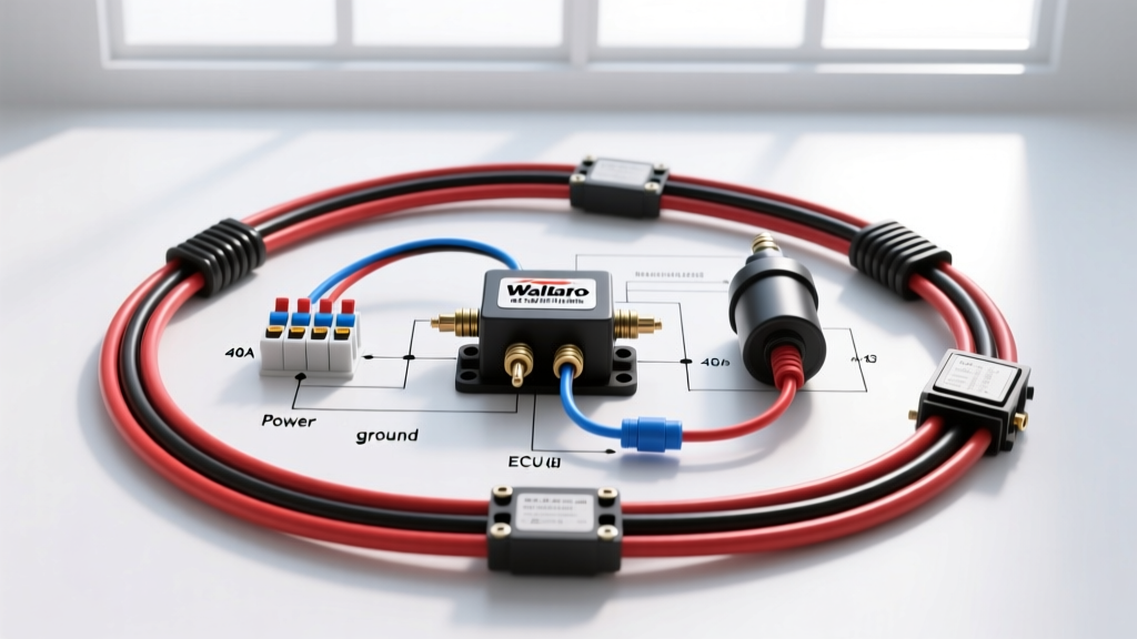
Upgrading the OEM Fuel Pump Wiring Diagram for High-Flow EFI Builds
When transitioning from a naturally aspirated street car to a forced-induction, E85-dedicated, or high-horsepower EFI build, the factory fuel delivery system is almost always the first bottleneck. While upgrading to a high-flow pump like the Walbro 450 (F90000274) or AEM 340 is standard practice, relying on the factory fuel pump wiring diagram is a recipe for melted connectors, severe voltage drop, and catastrophic lean conditions under boost. Modern high-amperage fuel pumps demand a dedicated, heavy-gauge power supply that factory harnesses simply cannot provide.
In this comprehensive upgrade guide, we break down the limitations of OEM wiring, provide a complete high-flow fuel pump relay wiring diagram, and detail the exact AWG specifications, crimping standards, and pinouts required to keep your EFI system running safely at peak fuel pressure.
Why the Factory Fuel Pump Wiring Diagram Fails Under High Load
Most OEM fuel pump circuits from the 1990s and 2000s utilize 16 AWG or 14 AWG wiring routed through a complex network of inertia switches, anti-theft modules, and factory relay boxes (such as Ford's Constant Control Relay Module or GM's rear-integration modules). These circuits were engineered for a 7 to 10-amp draw typical of a stock 155 LPH pump.
A modern brushless or high-amperage brushed pump can pull 15 to 25 amps continuously at base pressure, and spike well over 30 amps on startup or under high boost when fuel pressure demand increases. According to SAE J1128 standards for Low Tension Primary Cable, pushing 25 amps through 14 feet of 16 AWG wire results in a massive voltage drop. This not only starves the pump of the voltage it needs to reach its advertised flow rate, but it also turns the factory wiring into a heating element, melting OEM inertia switches and bulkhead connectors.
The Physics of Voltage Drop in Fuel Circuits
Electric fuel pumps are highly sensitive to voltage. A Walbro 450 LPH pump rated at 670 LPH at 40 PSI requires 13.5V to achieve that flow. If your OEM wiring drops the voltage to 11.5V under load, your fuel flow can decrease by over 20%, causing your ECU to hit fuel cut or pull timing to prevent detonation. By rewriting the fuel pump wiring diagram to include a dedicated 40A relay and 10 AWG power wire, you reduce voltage drop to less than 0.2V, ensuring maximum pump output.
High-Flow Fuel Pump Relay Harness Specifications
To execute this modification, you will need to build or purchase a heavy-duty relay harness. Below is the exact specification chart for a universal high-flow fuel pump upgrade.
| Circuit Function | Wire Gauge (AWG) | Recommended Color | Max Amperage | Fuse / Protection |
|---|---|---|---|---|
| Battery to Relay (Pin 30) | 10 AWG | Red | 40A | 30A MAXI Fuse (within 18 inches of battery) |
| Relay to Pump (Pin 87) | 10 AWG | Red | 35A | None (Protected by main fuse) |
| Pump Ground to Chassis | 10 AWG | Black | 35A | N/A (Ensure bare metal contact) |
| OEM Trigger to Relay (Pin 85) | 16 AWG | Blue | 5A | Tapped into OEM pump + wire |
| Relay Ground (Pin 86) | 16 AWG | Black | 5A | N/A (Ground to clean chassis) |
Step-by-Step Relay Upgrade Wiring Procedure
This procedure utilizes a standard Bosch-style ISO mini 5-pin relay (Pins 30, 87, 85, 86, and 87a). For a fuel pump, you will only use the 4 pins associated with a single-pole, single-throw (SPST) circuit, ignoring Pin 87a.
1. Routing the Heavy Gauge Power (Pins 30 and 87)
Run a continuous length of 10 AWG primary wire from the positive battery terminal to the engine bay or trunk-mounted relay location. Critical: You must install a 30A MAXI fuse holder within 18 inches of the battery positive terminal. If a short occurs near the battery and this fuse is missing, the 10 AWG wire will weld itself to the chassis and start an electrical fire. From the relay output (Pin 87), route the 10 AWG wire down the frame rail, securing it with UV-resistant zip ties and split loom tubing to protect against road debris and exhaust heat.
2. Tapping the OEM Trigger Signal (Pin 85)
Locate the factory fuel pump power wire near the ECU, CCRM, or rear harness bulkhead. Using a proper Posi-Tap or by cutting, soldering, and sealing with adhesive-lined heat shrink, tap your 16 AWG Blue trigger wire. This wire will carry less than 1 amp of current simply to energize the relay coil, meaning the factory wiring will no longer experience thermal overload. Connect this to Relay Pin 85.
3. Establishing Clean Grounds (Pin 86 and Pump Ground)
Relay chatter is a common issue in aftermarket fuel pump wiring diagrams. This occurs when the relay coil ground (Pin 86) shares a ground path with high-current accessories, causing voltage fluctuations. Run the 16 AWG ground wire from Pin 86 to a dedicated, sanded-to-bare-metal chassis point. Similarly, the 10 AWG pump ground must be bolted directly to the chassis or subframe near the fuel tank, completely bypassing any factory ground splices.
Upgrading the Fuel Pump Hat Pigtail
Even with a perfect 10 AWG relay harness, the modification will fail if you do not upgrade the connector at the fuel pump hat. The factory OEM connectors (often small 1.5mm or 2.0mm terminals) are not rated for 20+ amps. When installing a Walbro 450 or AEM 340, you must cut off the OEM pigtail and install a Delphi Weather-Pack or Metri-Pack 280 2-pin connector.
- Terminal Crimping: Use an open-barrel crimping tool (such as the TE Connectivity or Titan ratcheting crimpers) to affix the terminals to the 10 AWG wire. Never solder fuel pump pigtail connections; the solder can wick into the wire strands, creating a rigid point that will snap under the vibration of the fuel tank.
- Sealing: Ensure the silicone weather seals are pushed down to the wire insulation before crimping to maintain the IP67 waterproof rating inside the fuel tank environment.
- Dielectric Grease: Apply a small amount of dielectric grease to the terminals before mating to prevent corrosion from fuel vapors.
For further reference on proper terminal crimping and weather-sealing, consult the AEM Fuel Pump Installation Guidelines, which emphasize the necessity of heavy-duty pigtails for their 340 LPH units.
Troubleshooting Voltage Drop and Relay Chatter
Once the upgraded fuel pump wiring diagram is implemented, you must validate the circuit with a digital multimeter before starting the engine.
The Voltage Drop Test
Set your multimeter to DC Volts. Place the positive probe on the battery positive terminal and the negative probe on the fuel pump positive terminal (back-pinned at the Weather-Pack connector). Turn the key to the 'ON' position to prime the pump.
- Acceptable Drop: 0.1V to 0.3V
- Marginal Drop: 0.4V to 0.6V (Check for loose crimps or undersized wire)
- Failure Drop: 0.7V or higher (Indicates a bad ground, corroded bulkhead, or failing relay contacts)
Diagnosing Relay Chatter
If your relay rapidly clicks on and off during the prime cycle, you likely have a voltage drop on the trigger side (Pin 85) or a poor ground on the coil side (Pin 86). The ECU or factory relay may be using Pulse Width Modulation (PWM) or a voltage-reducing resistor module to control the stock pump. If your vehicle uses a PWM fuel pump controller (common in modern GM and Ford EcoBoost applications), you cannot simply tap the OEM wire for a trigger. You must use a dedicated 12V trigger source from the EFI controller (such as an unused output on a Holley Terminator X or Dominator ECU) or wire a manual toggle switch for the relay trigger to ensure a solid 12V signal to the Bosch relay coil.
Summary
Ignoring the limitations of the factory fuel pump wiring diagram is one of the most common mistakes in high-horsepower EFI tuning. By implementing a dedicated 10 AWG relay harness, upgrading the fuel tank pigtail to a Weather-Pack connector, and validating the circuit with a voltage drop test, you ensure that your high-flow fuel pump receives the consistent voltage required to keep your engine safe, rich, and powerful under extreme boost conditions.