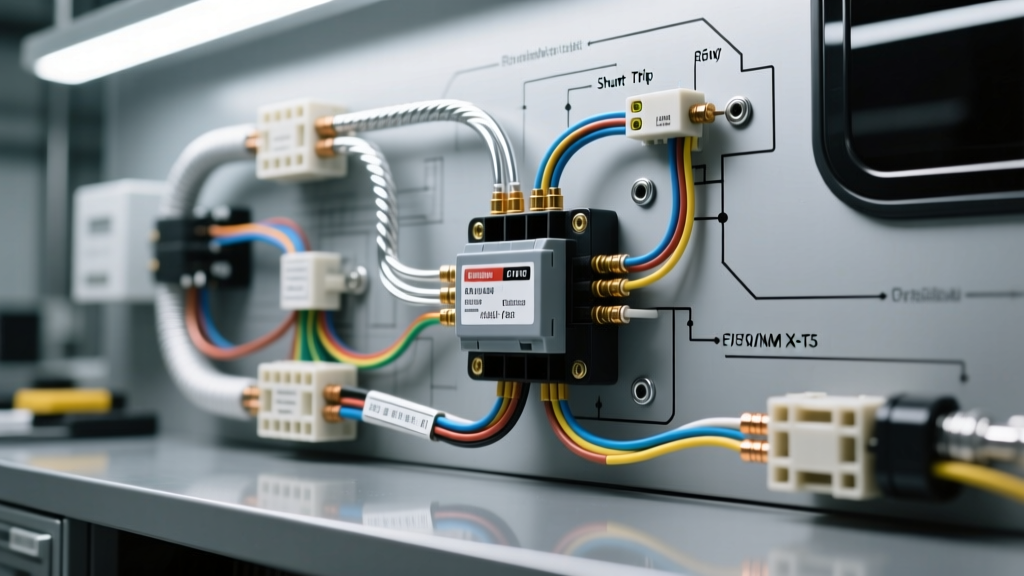
Automotive Applications for Shunt Trip Breakers
While the term "shunt trip breaker" is most commonly associated with commercial building electrical panels, the exact same electromechanical principle is heavily utilized in advanced automotive wiring. In modern Electric Vehicles (EVs), heavy-duty RVs, and custom off-grid expedition trucks, a remote-trip DC contactor or latching shunt breaker serves as the critical emergency disconnect. These devices are integrated into First Responder Loops, fire suppression systems, and Battery Management System (BMS) fail-safes to instantly sever the connection between the high-voltage battery pack and the vehicle's inverters or DC distribution buses.
Misinterpreting the wiring diagram for shunt trip breaker assemblies in a 12V/48V/800V automotive environment can lead to catastrophic results. Unlike a standard AC panel breaker, automotive shunt trips must withstand severe vibration, extreme thermal cycling, and high electromagnetic interference (EMI). This guide details the correct schematic configurations, pinouts, and the most dangerous wiring mistakes technicians make when installing or servicing these vital safety components.
Standard Wiring Diagram for Shunt Trip Breaker (12V Control / High-Amp Load)
In automotive applications, the shunt trip breaker utilizes a low-current 12V DC control circuit to actuate a mechanical latch that opens a high-current load path. Below is the standard schematic logic for an EV emergency disconnect or RV main battery kill switch.
Pinout and Terminal Configuration
- Terminal A1 (Coil +): Receives 12V DC from the Body Control Module (BCM), BMS, or manual emergency push-button switch. Wire Color: Yellow (SAE standard for supplemental restraint/safety circuits) or Red with a Yellow tracer.
- Terminal A2 (Coil -): Ground path for the trip coil. Wire Color: Black. Must be grounded to a dedicated chassis star-point, not daisy-chained.
- Terminal L1 (Line In): High-current input from the battery positive busbar. Torque spec: 15-25 Nm depending on stud size.
- Terminal L2 (Load Out): High-current output to the main fuse block, inverter, or distribution bus.
- Auxiliary Contacts (Optional 12/14): Low-current feedback switches (usually 12V, 2A max) used to signal the BMS or telematics unit that the breaker has physically tripped.
5 Fatal Wiring Mistakes and Safety Warnings
When consulting a wiring diagram for shunt trip breaker installations, technicians often apply standard relay logic to a device that requires specialized safety considerations. Avoid these five critical errors.
1. Undersizing the Trip Coil Control Wire
The electromagnetic coil inside a heavy-duty shunt trip requires a massive, momentary inrush current (often 15 to 30 amps for 50-100 milliseconds) to generate the magnetic force required to snap the mechanical latch open. A common mistake is wiring the A1/A2 coil terminals with standard 18 AWG signal wire. The voltage drop across 10 feet of 18 AWG wire during the inrush spike will starve the coil, resulting in a "mushy" trip where the contacts arc internally instead of snapping open, ultimately welding the contacts shut. Correction: Always use a minimum of 14 AWG (or 12 AWG for runs over 15 feet) for the trip coil control circuit, as per SAE J1128 high-temperature wire specifications.
2. Omitting the Flyback Suppression Diode
The trip coil is a highly inductive load. When the control circuit opens (or the BMS cuts the ground path after a successful trip), the collapsing magnetic field generates an inductive voltage spike (back-EMF) that can exceed 150V. In a sensitive EV environment, this spike will travel back up the control wire and instantly fry the driver transistor inside the BMS or BCM. Correction: A flyback diode (e.g., 1N5408, rated for 3A/1000V) must be installed in parallel with the A1 and A2 coil terminals, with the diode cathode (stripe) facing the 12V positive source. This provides a safe recirculation path for the inductive spike.
3. Routing Control Wires with High-Voltage Cables
In EV conversions and hybrid platforms, the orange high-voltage (HV) cables carry hundreds of amps, generating severe electromagnetic fields. Routing the 12V shunt trip control wires in the same loom or conduit violates SAE J1113 EMI immunity standards. A voltage spike induced by the HV inverter switching can falsely trigger the shunt trip, killing the vehicle's propulsion system at highway speeds. Correction: Maintain a minimum physical separation of 200mm (8 inches) between HV orange cables and the 12V shunt trip control harness. If crossing is unavoidable, route the wires at a strict 90-degree angle.
4. Confusing Continuous Duty Solenoids with Momentary Shunts
Many DIY RV builders and junior technicians mistake a continuous-duty starter solenoid for a shunt trip breaker. A standard solenoid requires constant voltage to remain closed; if power is lost, it opens. A true shunt trip breaker is a latching device. It requires only a momentary 12V pulse to trip open, and it remains mechanically latched in the open position until manually reset. Wiring a continuous-duty solenoid as a fire-safety kill switch means that if the vehicle's main battery is destroyed in a crash, the solenoid loses power and defaults to the wrong state, or fails to isolate a secondary battery bank.
5. Improper Torque on High-Current Busbars
The L1 and L2 terminals on an automotive shunt trip breaker are typically M8 or M10 threaded studs. Using standard hardware store washers or failing to use a calibrated torque wrench leads to micro-arcing under high DC loads (e.g., 300A inverter draw). This creates immense localized heat, melting the breaker casing and defeating the internal arc chute. Correction: Use only Belleville (conical spring) washers to maintain clamping force during thermal expansion cycles, and torque to the manufacturer's exact specification (typically 15 Nm for M8, 25 Nm for M10).
Wire Gauge and Connector Specification Chart
| Circuit Path | Recommended AWG | Insulation Type | Connector / Termination | Max Continuous Load |
|---|---|---|---|---|
| Trip Coil Control (A1/A2) | 14 AWG - 12 AWG | SAE J1128 (GXL/TXL) | Deutsch DT 2-Pin or Weather-Pack | 30A (Momentary Inrush) |
| Auxiliary Feedback (12/14) | 18 AWG | SAE J1128 (GXL) | Molex MX150 or OEM BCM Plug | 2A Continuous |
| Main Load Path (L1/L2) - 200A | 1/0 AWG | SAE J1127 or EV Orange Shielded | Crimped Copper Ring Terminal (M8) | 200A Continuous |
| Main Load Path (L1/L2) - 400A | 3/0 AWG or 4/0 AWG | SAE J1127 or EV Orange Shielded | Crimped Copper Ring Terminal (M10) | 400A Continuous |
Diagnostic Decision Tree: Shunt Trip Fails to Activate
When the BMS commands a disconnect or the manual emergency button is pressed, but the high-voltage circuit remains live, follow this diagnostic sequence to isolate the fault without compromising safety.
- Step 1: Verify Control Voltage at A1. Use a digital multimeter (DMM) to check for 12V+ at the A1 terminal during the trip command. If 0V, the fault is upstream (BCM, relay, or broken wire). If 12V is present, proceed to Step 2.
- Step 2: Check Coil Ground at A2. Measure resistance between A2 and the chassis star-point. It should be less than 0.5 ohms. High resistance indicates a corroded ground ring terminal.
- Step 3: Measure Coil Resistance. Disconnect the control harness. Measure resistance across A1 and A2 on the breaker itself. A healthy heavy-duty shunt coil typically reads between 2.0 and 5.0 ohms. An infinite reading (OL) indicates an open internal coil winding; the breaker must be replaced.
- Step 4: Inspect Mechanical Latch Bind. If the coil clicks audibly but the main contacts do not open, the mechanical latch is bound. This is often caused by overtightening the L1/L2 busbars, which warps the breaker casing and creates friction on the internal trip bar. Loosen the main lugs slightly and test again.
- Step 5: Verify Auxiliary Feedback. If the breaker physically trips but the BMS throws a "Disconnect Failure" code, the internal auxiliary micro-switches (Terminals 12/14) have failed or the feedback wiring is severed.
Authoritative References
For further reading on high-voltage safety, wire specifications, and emergency disconnect protocols, consult the following industry standards:
- SAE International J2990 - Hybrid and EV First Responder Safety and Emergency Disconnect Guidelines.
- NFPA 70 (National Electrical Code) - Article 750 covering DC Microgrids, EV infrastructure, and shunt trip requirements for fire safety integration.
- SAE J1128 - Standard for Low Tension Primary Cable specifications, crucial for selecting the correct control wire insulation for under-hood automotive environments.