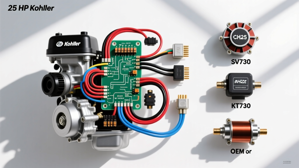
Navigating the 25 HP Kohler Engine Wiring Diagram PDF for Repowers and Repairs
When commercial landscapers, fleet mechanics, and DIY tractor enthusiasts search for a 25 HP Kohler engine wiring diagram PDF, they are rarely just looking for a basic schematic. Typically, they are in the middle of a complex engine repower, diagnosing a parasitic battery draw, or replacing a melted main wiring harness on a zero-turn mower (ZTR). Kohler’s 25-horsepower twin-cylinder lineup spans several distinct engine families, each with unique electrical architectures, stator outputs, and ignition kill circuits.
Selecting the correct replacement wiring harness, stator, or voltage regulator requires more than just matching the horsepower rating. A harness designed for a Kohler Command Pro CH25 will not seamlessly plug into a Courage SV730 or a 7000 Series KT730 without significant splicing and pin-swapping. This product comparison and selection guide breaks down the electrical platforms of Kohler’s 25 HP engines, helping you choose the exact OEM or aftermarket wiring components required for a reliable, heat-resistant repair.
Identifying Your 25 HP Kohler Electrical Platform
Before ordering a replacement harness based on a generic wiring diagram, you must identify the specific engine family. Kohler produced three primary 25 HP (or closely related) platforms that dominate the commercial and residential mower market. Their wiring topologies differ significantly.
1. Kohler Command Pro CH25 (Commercial Grade)
The CH25 is the gold standard for commercial ZTRs (e.g., Scag, Exmark, Gravely). It utilizes a heavy-duty wiring harness with high-temperature TXL insulation. Most CH25 engines use a Module Discharge Ignition (MDI) or a Smart Spark Arrestor Module (SAM). The SAM requires a dedicated 12V power feed and a specific ground-kill circuit. If your wiring diagram PDF shows a SAM module, you must select a harness with the corresponding 4-pin SAM connector, not a standard 2-pin magneto kill plug.
2. Kohler Courage SV730 (Residential/Light Commercial)
The SV730 is a cost-optimized version of the Command series. While the block shares similarities, the electrical system is often simplified. The Courage series typically uses a lower-amperage stator and a simplified ignition switch wiring loop. Aftermarket harnesses designed for the SV730 often omit the heavy-duty relays found on the CH25, making them unsuitable for commercial mowers with high-draw PTO clutches.
3. Kohler 7000 Series KT730 (Prosumer/Commercial)
The KT730 represents Kohler’s modern evolution, featuring updated cooling and simplified diagnostics. Wiring diagrams for the KT730 often integrate the voltage regulator and stator routing more tightly into the main chassis harness of the host mower, rather than utilizing a standalone engine pigtail. When repowering with a KT730, you often need an adapter harness to bridge the engine’s modern EFI or carburetor solenoid wiring to older mower chassis.
Stator, Regulator, and Harness Selection Chart
One of the most common mistakes when reading a 25 HP Kohler engine wiring diagram PDF is mismatching the stator output with the voltage regulator and the B+ wire gauge. Upgrading to a higher-amp stator without upgrading the harness will result in melted connectors and potential electrical fires. Use the comparison chart below to select the correct components.
| Engine Platform | Stator Part # | Amp Output | Regulator Part # | Required B+ Wire Gauge | AC Wire Color Code |
|---|---|---|---|---|---|
| Command Pro CH25 | 239 27 219-S | 20 Amp | 257 57 11-S | 10 AWG (TXL) | Yellow / Yellow |
| Courage SV730 | 32 08 303-S | 15 Amp | 25 75 53-S | 12 AWG (TXL) | Yellow / Yellow |
| 7000 Series KT730 | 32 08 305-S | 20 Amp | 25 75 53-S | 10 AWG (TXL) | Purple / White |
| CH25 EFI (Fuel Inj.) | 239 27 220-S | 30 Amp | 25 75 55-S | 8 AWG (TXL) | Yellow / Yellow |
Decoding the Wiring Diagram: Critical Pinouts and Color Codes
When splicing a new harness or adapting an engine to a non-standard chassis, understanding the exact wire color codes and pin configurations is vital. Based on official Kohler technical publications, here are the standard wire assignments for 25 HP carbureted twins.
The 3-Pin Voltage Regulator Connector
The voltage regulator is the most frequent failure point on Kohler twins due to heat soak and poor grounding. The standard 3-pin AMP/Molex weatherpack connector uses the following pinout:
- Pin 1 (Outer): Yellow Wire – AC Input from Stator
- Pin 2 (Center): Red Wire – DC B+ Output (Fused 12V to Battery)
- Pin 3 (Outer): Yellow Wire – AC Input from Stator
Expert Note: The regulator case must be grounded to the engine block. If the mounting bolts are corroded or painted over, the regulator will fail to rectify the AC voltage, pushing raw AC current into the battery and boiling the electrolyte. Always use a star washer and bare metal contact for regulator mounting.
Ignition and Fuel Solenoid Circuits
- White Wire (Ignition Kill): On standard magneto/MDI systems, the ignition modules fire when isolated from ground. To kill the engine, the ignition switch grounds the White wire. Never apply 12V to the White kill wire; doing so will instantly destroy the ignition modules.
- Purple Wire (12V Accessory/Solenoid): This wire supplies 12V to the carburetor fuel shut-off solenoid and the PTO clutch relay. It requires a 14 AWG wire to handle the inrush current of the solenoid.
OEM vs. Aftermarket Wiring Harness Kits: Which Should You Buy?
When your wiring diagram reveals a melted harness, you face a critical purchasing decision: OEM Kohler replacement or an aftermarket universal kit.
OEM Kohler Harnesses (e.g., Part # 247 55 211-S)
OEM harnesses are built to SAE J1128 specifications, utilizing TXL (Cross-linked Polyethylene) wire insulation. TXL is rated for continuous operation at 125°C (257°F), which is mandatory for wires routed over the hot cylinder heads of an air-cooled V-twin. The connectors are genuine Deutsch or high-grade AMP seals, preventing moisture ingress and green corrosion.
Aftermarket / Universal Repower Harnesses
Cheap aftermarket harnesses found on eBay or Amazon often use standard PVC-insulated wire. PVC becomes brittle and melts at temperatures exceeding 105°C. When routed near the Kohler exhaust manifold or valve covers, PVC wire will short to the block within a single mowing season. If you must use an aftermarket harness, verify that the seller explicitly states the use of TXL or GXL high-temp wire, and plan to wrap the harness in split-loom and reflective heat-sleeving.
Troubleshooting the 25 HP Charging Circuit
Before replacing the stator or regulator based on a wiring diagram, perform these definitive multimeter tests to isolate the failure.
- Stator AC Output Test: Disconnect the 3-pin regulator connector. Set your multimeter to AC Volts. Probe the two Yellow (or Purple/White) wires in the engine-side harness. Start the engine and run at 3600 RPM. A healthy 20A stator should produce 30 to 60 VAC. If output is zero or below 20 VAC, the stator is burnt out or a flywheel magnet has sheared.
- Regulator DC Output Test: Reconnect the regulator. Set the multimeter to DC Volts. Probe the center Red B+ wire (back-pierce the connector). At 3600 RPM, you should read 13.8V to 14.7V DC. If AC voltage is present on the Red wire, the internal diodes of the regulator have failed.
- Voltage Drop Test (Crucial for Repowers): If the battery isn't charging but the stator and regulator test fine, you have a harness resistance issue. Set the multimeter to DC Volts. Place the positive probe on the regulator's Red wire terminal and the negative probe on the battery's positive post. Run the engine at 3600 RPM. A reading greater than 0.2V indicates high resistance in the B+ wire, usually due to a corroded inline fuse holder or an undersized aftermarket wire gauge.
Final Selection Advice
Downloading a 25 HP Kohler engine wiring diagram PDF is only the first step in a successful repair or repower. Always cross-reference your engine's specific Spec Number (found on the silver valve cover decal) with the stator amperage and ignition type (SAM vs. MDI). Invest in TXL-rated wiring, use open-barrel crimpers for weatherpack terminals, and ensure flawless engine-to-chassis grounding to guarantee your Kohler twin’s electrical system survives the harshest commercial mowing conditions.