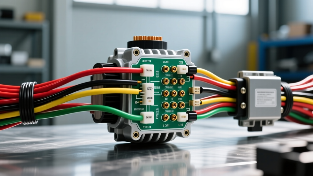
The A35 Chassis Intelligent Charging Architecture
Working on the charging system of the A35-chassis VQ35DE engine requires a fundamental shift in diagnostic thinking. Unlike older vehicles where the alternator simply outputs a static 14.2 volts whenever the engine is running, the 2011 Nissan Maxima alternator connector wiring diagram reveals a highly sophisticated, ECM-controlled variable voltage charging system. The Engine Control Module (ECM) and the Intelligent Power Distribution Module Engine Room (IPDM-ER) constantly monitor battery temperature, electrical load, and engine torque to adjust alternator output dynamically.
Because of this data-bus-level integration, treating the alternator harness like a standard 1990s charging circuit is a fast track to catastrophic module failure. Below, we detail the exact pinout specifications, critical safety warnings, and the most common fatal mistakes technicians and DIYers make when diagnosing or repairing this specific harness.
2011 Nissan Maxima Alternator Pinout Specifications
The 2011 Maxima utilizes a 4-pin Sumitomo-style waterproof connector. The wire gauges are relatively small (18 AWG) because they carry low-amperage signal and logic voltages, not the main charging current. The main charging current travels through the B+ terminal via a heavy-duty 4 AWG cable routed to the IPDM-ER fusible link block.
| Pin | Terminal ID | Wire Color | Gauge | Function & Destination |
|---|---|---|---|---|
| 1 | S (Sense) | White (W) or Red (R) | 18 AWG | Battery voltage sense line. Routes directly to the battery positive terminal or main fusible link block to monitor true system voltage. |
| 2 | L (Lamp) | Yellow/Red (Y/R) | 18 AWG | Charge warning lamp signal. Routes to the IPDM-ER and BCM to trigger the dashboard battery light if output drops below threshold. |
| 3 | FR (Field Rate) | Green/Black (G/B) | 18 AWG | Duty cycle signal sent to the ECM. Informs the ECM of current alternator load so it can adjust idle air control to prevent engine stalling. |
| 4 | C (Control) | Blue/White (L/W) | 18 AWG | ECM command signal. The ECM pulses this line to command the internal voltage regulator to raise or lower output (typically 13.0V to 14.5V). |
Critical Safety Warnings Before Disconnecting
Before probing any wires referenced in the 2011 Nissan Maxima alternator connector wiring diagram, you must adhere to strict high-amperage safety protocols. The VQ35DE alternator is rated for 150 Amps. A short circuit at the B+ terminal can instantly weld tools, ignite harness insulation, and cause severe burns.
- Disconnect the Negative Terminal First: Always isolate the negative battery cable and wait a minimum of 3 minutes before touching the alternator harness. This allows the IPDM-ER and ECM capacitors to discharge, preventing voltage spikes when connectors are separated.
- B+ Torque Specifications: The B+ nut on the alternator must be torqued to exactly 10.8 N·m (96 in-lb). Overtightening will strip the soft brass threads on the alternator casing; undertightening will cause micro-arcing, leading to localized heat melt and a P0560 (System Voltage) code.
- Exhaust Proximity Hazard: The alternator is mounted low on the passenger side of the VQ35DE, in close proximity to the primary catalytic converter. Never route replacement harnesses without OEM-style braided heat shielding. Standard corrugated plastic loom will melt and expose the 18 AWG signal wires to the exhaust manifold.
4 Fatal Wiring Mistakes That Destroy the ECM
When referencing the 2011 Nissan Maxima alternator connector wiring diagram for troubleshooting, avoiding these common errors is paramount to saving thousands of dollars in module replacement costs.
Mistake #1: Piercing the 'C' (Control) Wire with an Incandescent Test Light
This is the most common and devastating mistake. The 'C' terminal is a logic-level control circuit driven by a sensitive transistor inside the ECM. If you pierce the Blue/White wire with a standard incandescent test light to check for "power," the test light will draw excessive current and backfeed voltage, instantly frying the ECM's internal driver. Never use a test light on Pin 3 or Pin 4. Always use a high-impedance Digital Multimeter (DMM) or an automotive oscilloscope to read the PWM duty cycle.
Mistake #2: Aftermarket Pigtail Voltage Drop on the 'S' (Sense) Circuit
Many DIYers buy cheap, universal alternator pigtails from auto parts stores when the OEM connector locking tab breaks (a common issue due to engine heat). These universal pigtails often use undersized 20 or 22 AWG wire and poor-quality crimp terminals. Because the 'S' (Sense) wire dictates the alternator's voltage output based on micro-volt calculations, a poor crimp introduces a 0.3V to 0.5V voltage drop. The alternator "thinks" the battery is fully charged when it isn't, resulting in chronic undercharging and premature battery sulfation. Always use OEM Sumitomo TS 090 terminals and adhesive-lined marine heat shrink.
Mistake #3: Ignoring the 150A IPDM-ER Fusible Link
When an alternator fails to charge, tunnel vision often leads mechanics to replace the alternator without checking the IPDM-ER. The main B+ wire routes into the IPDM-ER box located near the battery, passing through a 150A high-current fusible link. If the alternator diode bridge shorts to ground, this link blows. If you replace the alternator but fail to check the IPDM-ER fusible link block, the new alternator will not output current, leading to a misdiagnosis.
Mistake #4: Misinterpreting the 'FR' Duty Cycle Signal
The Green/Black 'FR' wire outputs a variable duty cycle signal (usually between 10% and 90%) to tell the ECM how hard the alternator is working. A common mistake is measuring this wire with a standard multimeter set to DC Volts and assuming the alternator is "failing" because the voltage fluctuates wildly or reads an average of 7 volts. This is normal. You must use an oscilloscope to view the square wave. According to Nissan Factory Service Manuals, a flat 0V or solid 12V square wave indicates an open or shorted internal regulator, not a fluctuating DC voltage.
Proper Diagnostic Protocol: Step-by-Step Voltage Drop Testing
To safely verify the integrity of the wiring diagram without back-probing and damaging the waterproof seals, follow this voltage drop sequence:
- Prep the System: Turn the ignition ON, engine OFF. Turn on the headlights and rear defroster to place a load on the battery.
- Test the Sense Wire (Pin 1): Set your DMM to DC Volts. Place the red probe on the battery positive post and the black probe on the alternator B+ terminal. A reading above 0.1V indicates excessive resistance in the main charge cable or IPDM connections.
- Test the Ground Path: Place the red probe on the alternator casing (bare metal) and the black probe on the battery negative post. Crank the engine. Any reading over 0.05V means the engine block ground straps are corroded, which will cause the ECM to miscalculate the 'C' pin signal reference.
- Verify ECM Command (Pin 4): Start the engine. Connect your oscilloscope to the Blue/White wire. You should see a PWM square wave. If the battery is low, the ECM will command a high duty cycle (approaching 14.5V output). If the battery is warm and fully charged, the ECM will drop the duty cycle to reduce parasitic drag on the VQ35DE serpentine belt.
Authoritative References & Further Reading
For comprehensive electrical schematics, connector end-views, and IPDM-ER routing charts, technicians should consult the following authoritative resources:
- Nissan Factory Service Manuals (FSM) - The definitive source for A35 chassis wiring diagrams, pinouts, and ECM logic tables.
- SAE J1113 Standards - Society of Automotive Engineers guidelines on electromagnetic compatibility and wiring harness shielding requirements for high-heat engine bays.
- Haynes Nissan Repair Manuals - Excellent for visual references of the IPDM-ER fusible link layout and alternator removal torque sequences.
By respecting the intelligent design of the VQ35DE charging system and strictly adhering to the 2011 Nissan Maxima alternator connector wiring diagram specifications, you can accurately diagnose electrical faults without risking collateral damage to the vehicle's expensive control modules.