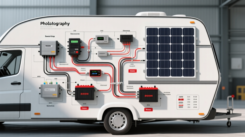
Integrating High-Capacity Inverters into Vehicle Platforms
When converting a Ford Transit, Mercedes Sprinter, or Ram ProMaster into an overland expedition vehicle, designing a robust solar wiring diagram inverter system is the most critical electrical task. Unlike stationary off-grid cabins, vehicle-based systems must endure high-frequency vibrations, extreme thermal cycling, and complex interactions with the OEM alternator and CAN-bus networks. Selecting the right inverter topology and executing the wiring diagram to marine and automotive standards (such as ABYC E-11 and SAE J1128) ensures that sensitive ECU modules are not damaged by voltage spikes or harmonic distortion.
Inverter Topology Comparison: Pure Sine vs. Modified Sine
Before drafting your schematic, you must select the correct waveform. Modern vehicles feature sensitive onboard chargers, CPAP machines, and variable-speed compressor fridges that require a pure sine wave.
- Pure Sine Wave (PSW): Outputs a smooth, grid-identical AC waveform. Essential for vehicle integration to prevent harmonic interference with the OEM CAN-bus and infotainment systems.
- Modified Sine Wave (MSW): Outputs a stepped, blocky waveform. While cheaper, MSW inverters generate electromagnetic interference (EMI) that can induce noise into unshielded vehicle sensor harnesses (e.g., O2 sensors, ABS modules).
Product Comparison: Victron MultiPlus-II vs. Renogy 3000W
Below is a technical comparison of two dominant inverters used in camper van solar wiring diagrams, focusing on vehicle integration capabilities.
| Specification | Victron MultiPlus-II 12/3000 | Renogy 3000W Pure Sine |
|---|---|---|
| Continuous Power | 3000W (24V System Recommended) | 3000W (12V or 24V) |
| Transfer Switch Speed | < 20ms (UPS Function) | Standard (Not UPS rated) |
| Vehicle IGN Trigger | Yes (Via GX Device / Cerbo) | Hardware Switch / Remote Panel |
| DC Terminal Size | M8 Bolts (Accepts 2/0 AWG) | M8 Bolts (Accepts 2/0 AWG) |
| Neutral-Ground Bonding | Internal Relay (Switchable) | Fixed Internal Bond |
Decoding the Solar Wiring Diagram Inverter Layout
A professional solar wiring diagram inverter schematic for a vehicle is divided into three distinct subsystems: the DC input, the AC output/transfer, and the alternator charging integration.
1. DC Input Wiring and Overcurrent Protection
The connection between the lithium house bank and the inverter requires heavy-gauge, highly stranded wire to handle massive DC current draws while resisting vibration fatigue. For a 3000W inverter on a 12V system, peak current can exceed 280A.
- Wire Gauge: Use 2/0 AWG (70mm²) welding cable (SAE J1128 compliant). For 24V systems, 1/0 AWG is sufficient and reduces voltage drop.
- Fusing: Install a Class T fuse (300A or 400A) within 18 inches of the battery positive terminal. Class T fuses have a 20,000 AIC (Ampere Interrupting Capacity) rating, which is mandatory for lithium iron phosphate (LiFePO4) batteries that can deliver catastrophic short-circuit currents.
- Terminations: Use closed-end, adhesive-lined heat shrink ring terminals. Crimp with a hex-die hydraulic crimper. Torque M8 terminal nuts to 10-12 Nm to prevent thermal runaway at the busbar.
2. AC Output and Neutral-Ground Bonding
Wiring the AC side in a vehicle requires strict attention to Neutral-Ground (N-G) bonding. In a standard house, N-G is bonded at the main panel. In a vehicle, if your inverter has an internal bond and you wire it into an AC subpanel that also bonds N-G, you create a parallel neutral path, which is a severe shock hazard and violates RVIA/ABYC standards. Use 10 AWG stranded THHN wire for AC runs (Black for Hot, White for Neutral, Green for Ground).
The Fix: If using an inverter with a built-in transfer switch (like the Victron), utilize a panel with an isolated neutral bar. The inverter's internal relay will handle the N-G bond automatically when transitioning from shore power to battery inversion.
3. Alternator Integration and the IGN Signal
The most common failure in amateur solar wiring diagram inverter builds is the destruction of the vehicle's OEM alternator. Connecting a DC-DC charger directly to the starter battery without an ignition trigger will drain the chassis battery when the engine is off. Furthermore, you must upgrade the OEM alternator ground strap to 2/0 AWG to prevent ECU damage from high return currents.
- Ford Transit: Tap into the Upfitter Interface Module (UIM) under the driver's seat. Pin 4 of the UIM provides a 12V Run/Start signal. Run a 14 AWG wire from Pin 4 to the IGN terminal on your DC-DC charger.
- Mercedes Sprinter: Utilize the EK1 terminal block under the driver's seat pedestal. The D+ terminal provides an alternator-active signal, ensuring the DC-DC charger only pulls current when the alternator is actively generating voltage.
Calculating DC Voltage Drop for Transit Van Builds
Voltage drop is the silent killer of high-wattage inverter systems. The formula for DC voltage drop is: V_drop = (2 × L × I × R) / 1000, where L is the one-way wire length in feet, I is the peak current, and R is the wire resistance per 1000 feet. For a Ford Transit build where the battery bank is in the rear and the inverter is mounted mid-cabin, a 10-foot one-way run (20 feet total) using 2/0 AWG copper (0.156 ohms/1000ft) at 250A peak draw results in a 0.78V drop. While this seems small, if your resting battery voltage is 12.2V, a 0.78V drop pushes the inverter's input terminals down to 11.42V, dangerously close to the Low Voltage Disconnect (LVD) threshold. Always measure voltage at the inverter lugs under maximum load, not at the battery terminals.
Vehicle-Specific Wiring Nuances
Modern expedition vehicles utilize smart alternators and LIN-bus controlled battery management systems. If your solar wiring diagram inverter setup includes a high-amp DC-DC charger (e.g., 60A+), you must trick the OEM ECU into maintaining high alternator output.
For RAM ProMaster and late-model Sprinter vans, installing a Battery Sense module or wiring a manual dashboard toggle to the alternator's LIN-bus field wire forces the ECU into a high-charge profile (14.4V - 14.6V). Without this, the smart alternator will drop to 12.8V during highway cruising, effectively starving your inverter's DC-DC charging circuit and causing the system to shut down under load.
Furthermore, routing the DC-DC charger's data cables away from the vehicle's primary CAN-bus harness is critical. High-amperage DC switching inside the inverter can induce transient voltage spikes. Maintain a minimum 6-inch separation between 120V AC lines, heavy DC battery cables, and the OEM low-voltage sensor harnesses to prevent Check Engine Lights (CEL) or phantom ABS faults.
Troubleshooting Common Inverter Wiring Faults
| Symptom | Root Cause | Diagnostic & Fix |
|---|---|---|
| Inverter shuts down under heavy AC load (e.g., microwave) | Excessive DC voltage drop triggering Low Voltage Cutoff (LVC). | Measure voltage directly at inverter DC terminals under load. If it drops below 10.5V, upgrade from 2/0 to 4/0 AWG or shorten cable runs. |
| GFCI outlets in the van randomly trip | Improper Neutral-Ground bonding or EMI from modified sine wave. | Verify N-G bond is only occurring at one source. Ensure inverter chassis is grounded to the vehicle chassis with 6 AWG green wire. |
| Starter battery is dead after 2 days of camping | DC-DC charger IGN wire wired to constant 12V instead of switched. | Use a multimeter to test the IGN source wire with the key OFF. Move to OEM UIM/EK1 ignition-switched pin. |
Authoritative References & Standards
When engineering your system, always consult manufacturer documentation and industry standards to ensure safety and compliance:
- Victron Energy Official Wiring Diagrams & Manuals - Essential for MultiPlus transfer switch logic and Cerbo GX CAN-bus integration.
- ABYC (American Boat & Yacht Council) E-11 Standards - The gold standard for DC overcurrent protection, wire sizing, and vibration-resistant termination in mobile environments.
- SAE J1128 Low Tension Primary Cable Standard - Specifications for automotive-grade wire insulation and thermal ratings.