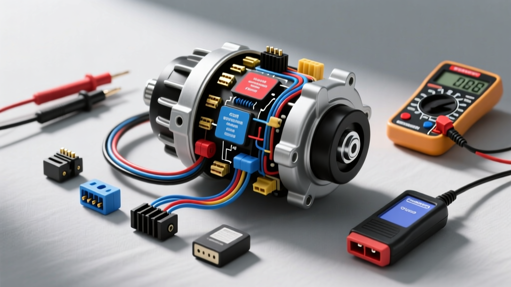
Understanding the A35 VQ35DE Smart Charging System
The 2009 Nissan Maxima, built on the A35 chassis and powered by the 3.5L VQ35DE V6 engine, utilizes a highly sophisticated ECM-controlled variable voltage charging system. Unlike older vehicles that relied on a simple internal voltage regulator set to a static 14.2 volts, the Maxima's Engine Control Module (ECM) actively monitors electrical load, battery state-of-charge, and engine torque demand. It then sends a Pulse Width Modulated (PWM) signal to the alternator's internal regulator to adjust output voltage dynamically between 115A and 150A.
When diagnosing a no-charge condition, battery boiling, or intermittent electrical gremlins, simply swapping the alternator is a costly gamble. A proper repair requires a thorough understanding of the 2009 Nissan Maxima alternator wiring diagram, an analysis of the required diagnostic tooling, and a realistic budget for OEM versus aftermarket components. This guide breaks down the exact pinouts, tool requirements, and cost analysis needed to execute a professional-grade charging system repair.
2009 Nissan Maxima Alternator Wiring Diagram & Pinout Data
The Denso alternator used in the 2009 Maxima features a heavy-gauge B+ output stud and a 4-pin Sumitomo sealed connector. However, only three terminals are typically populated in this specific application. Below is the exact pinout data, wire color coding, and circuit function derived from factory schematics.
| Terminal / Pin | Wire Color | AWG Size | Circuit Function & Destination |
|---|---|---|---|
| B+ (Stud) | Red / Black | 4 AWG | Main Battery Output. Routes to the IPDM-ER 120A fusible link and battery positive. |
| Pin 1 (S) | Black / Red | 16 AWG | Battery Sense. Provides direct battery voltage reference to the internal regulator. |
| Pin 2 (L) | Green / White | 20 AWG | Ignition / Charge Lamp. Receives 12V from the IPDM-ER when the ignition is ON. |
| Pin 3 (G) | Blue / Yellow | 20 AWG | Generator Control. Receives PWM duty cycle signal from the ECM (Pin 48 on ECM connector). |
| Pin 4 | N/A (Sealed) | N/A | Not Used. Cavity is sealed with a dummy plug to maintain weatherproofing. |
Note: Wire colors may vary slightly depending on the exact production month and whether the harness was subject to a mid-year running change. Always verify with a Digital Multimeter (DMM) against the vehicle's specific VIN.
Tool Requirements: Beyond the Basic Socket Set
Diagnosing a PWM-controlled charging system requires specialized electrical tools. Attempting to back-probe the Sumitomo connector with standard paperclips or sewing needles will spread the female terminals, causing intermittent connection issues that mimic a failing ECM. Here is the mandatory tooling list for this repair:
- Digital Multimeter with Duty Cycle (PWM): A standard DMM is insufficient for Pin 3. You need a meter capable of measuring frequency (Hz) and duty cycle (%). The Fluke 88V Automotive Multimeter is the industry standard for reading the ECM's alternating voltage signal.
- Sumitomo Terminal Extraction Tool: The alternator pigtail uses a Sumitomo 090-II series connector. You must use a specific terminal release tool (such as the OEMTOOLS 25263 or Lisle 30500) to depress the internal lance and remove pins without snapping the locking tab.
- 0.64mm Back-Probe Pins: Essential for piercing the weather seals at the rear of the connector to read live data while the engine is running, without damaging the terminal faces.
- Adhesive-Lined Heat Shrink & Open Barrel Crimpers: Per SAE J1128 Automotive Wire Standards, soldering is discouraged in high-vibration under-hood environments due to fatigue cracking. Open barrel crimps with marine-grade adhesive heat shrink are mandatory for any pigtail repairs.
- Inch-Pound Torque Wrench: The B+ terminal nut is easily over-torqued, which can crack the internal diode bridge or strip the stud. A precision torque wrench is required.
Cost Analysis: Parts, Pigtails, and Repair Budgets
Budgeting for a charging system repair on the A35 Maxima requires looking beyond just the alternator. The IPDM-ER (Intelligent Power Distribution Module Engine Room) and the wiring harness are frequent culprits in charging faults. Below is a realistic cost breakdown for a comprehensive repair.
| Component / Service | OEM / Professional Grade | Aftermarket / Budget | Notes |
|---|---|---|---|
| Alternator Assembly (150A) | $380 - $480 (Denso) | $160 - $230 (Reman) | OEM Denso is highly recommended. Remanufactured units often feature inferior voltage regulators that fail to interpret the ECM PWM signal correctly. |
| Alternator Pigtail Harness | $35 - $45 | $15 - $20 | Do not splice bare wires. Buy the OEM plug-and-play pigtail (Part # 24079-JK20A or equivalent) to ensure proper pin tension. |
| IPDM-ER 120A Fusible Link | $18 - $25 | $10 - $15 | If the B+ circuit shorted, this bolt-down fusible link in the IPDM must be replaced. |
| Terminal Repair Kit | $12 - $18 | N/A | Includes Sumitomo pins, seals, and dummy plugs. |
Total DIY Parts Budget: $425 - $560 (Using OEM Denso and new pigtail).
Labor Time (Professional): 1.8 to 2.2 hours (Book time), equating to roughly $250 - $350 in labor depending on local shop rates. The alternator is mounted high on the passenger side of the VQ35DE engine, requiring removal of the passenger wheel, inner fender liner, and drive belt for proper access.
Diagnostic Workflow: Testing the ECM PWM Signal
Before condemning the alternator, you must verify that the ECM is commanding the correct output. Follow this diagnostic sequence using your 2009 Nissan Maxima alternator wiring diagram:
- Verify the Sense Circuit (Pin 1): Back-probe the Black/Red wire with the engine off. It should read within 0.1V of the battery's resting voltage (approx. 12.4V - 12.6V). If this wire is broken or corroded, the alternator will default to a failsafe mode or overcharge the battery because it cannot 'see' the true battery voltage.
- Verify the Ignition Signal (Pin 2): Turn the key to the ON position (engine off). Back-probe the Green/White wire. You should see 12V. If missing, check the IPDM-ER for a blown 10A fuse or a faulty ignition relay.
- Analyze the ECM Control Signal (Pin 3): Start the engine. Connect your DMM to the Blue/Yellow wire, set to Duty Cycle (%). At idle with no electrical loads, the ECM may command a low duty cycle (resulting in ~13.1V to save fuel). Turn on the rear defroster, headlights, and HVAC blower to max. The duty cycle should shift, and the alternator output voltage should rise to 14.2V - 14.8V. If the voltage stays at 12.5V and the battery drains, but the PWM signal is present, the alternator's internal regulator is faulty.
Real-World Failure Modes & IPDM-ER Issues
As an automotive electrical specialist, I frequently see the A35 Maxima in the shop for charging issues that are entirely unrelated to the alternator itself. Be aware of these common failure modes:
1. B+ Terminal Corrosion and the Missing Boot
The 4 AWG Red/Black B+ cable connects to a 12mm stud on the alternator. From the factory, this stud is covered by a rubber weather boot. During previous belt changes or minor services, this boot is often torn or left off. Moisture and road salt infiltrate the crimp barrel, causing high resistance. This triggers the alternator to work harder, eventually melting the terminal. Always clean the terminal with a wire brush, apply dielectric grease, and torque the M10 nut to exactly 14 Nm (10 ft-lbs).
2. IPDM-ER Internal Relay Failure
The IPDM-ER module, located in the passenger side engine bay fuse box, controls the primary power distribution. The internal PCB traces and relays that supply power to the alternator's 'L' circuit and the main fusible link are prone to moisture intrusion if the IPDM lid seal degrades. If you have no 12V at Pin 2 (Green/White) and all fuses test good, the IPDM-ER unit itself may require replacement (Part # 284B7-JK000, approx. $350).
3. Alternator Mounting Bolt Torque Specs
The alternator grounds through its aluminum casing to the engine block. If the mounting bracket bolts are not torqued correctly, the alternator will seek a ground path through the wiring harness, melting the 20 AWG control wires. The upper M10 mounting bolt must be torqued to 45 Nm (33 ft-lbs), and the lower pivot bolt to 65 Nm (48 ft-lbs). Always clean the mating surfaces on the engine block with a brass wire brush before installation to ensure a flawless ground plane.
Conclusion
Repairing the charging system on a 2009 Nissan Maxima requires more than just unbolting a 150A Denso unit. By leveraging the correct 2009 Nissan Maxima alternator wiring diagram, utilizing PWM-capable diagnostic tools, and investing in OEM pigtails and proper crimping techniques, you can ensure a permanent fix. For further technical documentation, wiring schematics, and TSBs, professionals should consult the Nissan Technical Information System (NTIS) and reference DENSO Automotive Americas for specific regulator testing parameters.