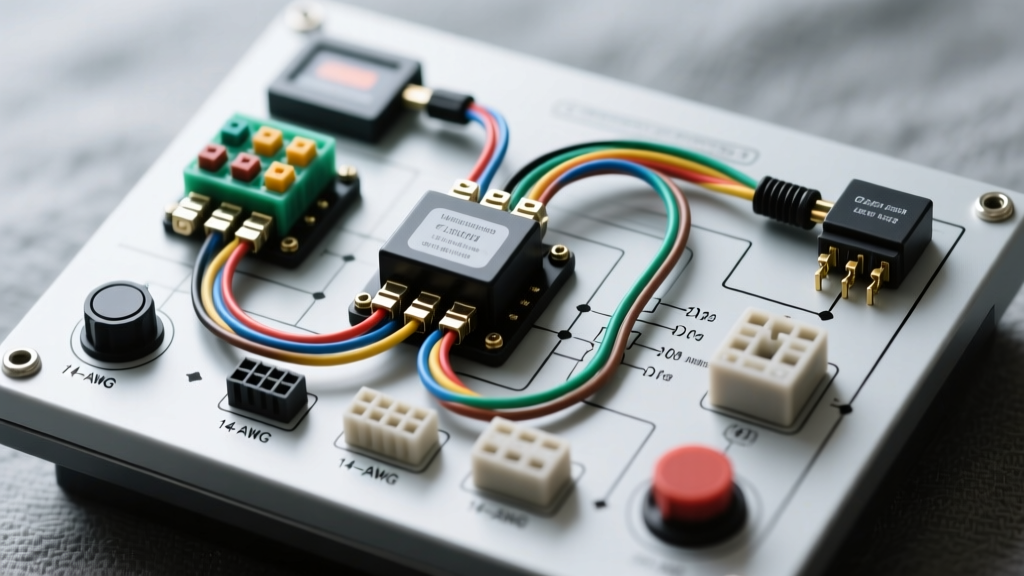
Decoding the Vehicle Wiring Diagram for Control Panel Setups
When outfitting an overland or off-road vehicle—such as a Jeep Wrangler JL, Toyota Tacoma, or Ford Bronco—adding auxiliary lighting, air compressors, and winch solenoids requires a centralized switching solution. Interpreting the correct wiring diagram for control panel relay integration is the difference between a reliable, weather-sealed electrical system and a melted harness. A standard 6-switch auxiliary control panel does not route high-amperage loads through the dashboard switches. Instead, the switches act as low-current triggers for a remote relay box. This guide provides a master-level breakdown of the schematic, wire gauging, and installation protocols required to properly integrate a control panel relay system into your vehicle's 12V DC architecture.
Anatomy of the Control Panel Wiring Schematic
A standard auxiliary relay box wiring diagram for control panel applications consists of four distinct sub-circuits. Understanding how these interact is critical before cutting or crimping a single wire.
- Main Power Feed (Battery to Relay Box): Supplies high-current 12V+ to the relay input pins.
- Switch Trigger Circuit (Dash to Relay Box): Carries low-current 12V+ from the cabin switch panel to the relay coils.
- Control Ground Circuit (Relay Coils to Chassis): Completes the electromagnetic circuit inside the relay.
- Load Output Circuit (Relay Box to Accessories): Delivers the switched high-current power to the end devices (e.g., LED light bars).
ISO Mini Relay Pinout Standards
Most high-quality automotive control panels utilize standard 4-pin or 5-pin ISO Mini Relays (ISO 7588-1). When reading your wiring diagram for control panel components, you must identify the DIN 72552 standard pin numbers stamped on the relay casing:
- Pin 30 (Common Input): Receives constant 12V+ from the main battery feed via a fused power block.
- Pin 87 (Normally Open Output): Sends 12V+ to the accessory load only when the relay coil is energized.
- Pin 86 (Coil Input): Receives the low-current 12V+ trigger signal from the dashboard switch panel.
- Pin 85 (Coil Ground): Grounds the relay coil. In advanced panels, this is routed to an ECU-triggered ground or a manual override switch.
- Pin 87a (Normally Closed - 5-pin only): Provides power when the relay is at rest. Rarely used in auxiliary lighting but common in winch-in/winch-out solenoid setups.
According to the Littelfuse Mini ISO Relay Datasheet, these relays are rated for up to 40A continuous load, but automotive best practices dictate derating to 75% (30A) to prevent thermal degradation of the internal contacts.
Step-by-Step Installation and Routing Guide
Step 1: Main Power and Ground Routing
The most common failure point in auxiliary electrical systems is voltage drop on the main power feed. For a 6-relay control panel capable of handling a combined 120A peak load, you must use 4 AWG or 6 AWG primary wire. We recommend SAE J1128 XLPE (Cross-Linked Polyethylene) insulated wire for its high-temperature resistance and thin wall profile, as outlined in the SAE J1128 Low Tension Primary Cable Standard.
- Battery Connection: Install an ANL or Class-T fuse within 7 inches of the positive battery terminal. For a 150A total system capacity, use a 125A ANL fuse.
- Grounding the Relay Box: Do not rely on self-tapping screws into painted sheet metal. Scour the chassis to bare metal, apply a conductive zinc-rich primer, and secure the 6 AWG ground wire using an M8 stainless steel ring terminal torqued to 10-12 Nm. Coat the terminal in dielectric grease to prevent galvanic corrosion.
Step 2: Firewall Pass-Through and Switch Harness
Running the switch trigger wires from the cabin-mounted control panel to the engine bay relay box requires a sealed firewall pass-through. Never pierce existing OEM rubber grommets with a pick. Instead, drill a dedicated 1-inch hole in a flat section of the firewall and install a marine-grade deck gland.
Use 18 AWG stranded copper for the switch trigger wires. To maintain a clean, OEM-style installation, terminate the cabin-side harness and engine-side harness with a Deutsch DT 12-pin connector. This allows you to unplug the entire dashboard control panel for maintenance without cutting wires. Ensure you use the proper DT extraction tool and crimp the pins using a precision hex-crimp tool, not standard pliers, to ensure optimal gas-tight wire-to-pin compression.
Step 3: Load Side Wiring and Weatherproofing
When routing the 12 AWG or 14 AWG load wires from Pin 87 to your accessories (e.g., a 40-inch LED light bar), utilize adhesive-lined dual-wall heat shrink. Standard PVC electrical tape will unravel in engine bay heat and UV exposure. Heat the shrink tubing to 120°C until the inner adhesive melts and seals the connection, achieving an IP67 waterproof rating.
Wire Gauge and Fuse Specification Chart
Proper wire sizing prevents voltage drop and mitigates fire risks. The following chart aligns with the Blue Sea Systems DC Circuit Wire Sizing Guide, assuming a standard 3% voltage drop limit at 13.8V over a 15-foot round-trip run.
| Accessory Type | Max Draw (Amps) | Wire Gauge (AWG) | Inline Fuse Size | Connector Type |
|---|---|---|---|---|
| LED Light Bar (40-inch) | 18A - 22A | 12 AWG | 25A Blade / MAXI | Deutsch DT 2-Pin |
| Portable Air Compressor | 30A - 35A | 10 AWG | 40A MAXI | Anderson SB50 |
| Winch Solenoid Contactor | 5A (Trigger only) | 14 AWG | 10A Mini | Weather-Pack 1-Way |
| Rock Lights (Set of 4) | 4A - 6A | 16 AWG | 10A Mini | Metri-Pack 150 |
| Under-hood Work Lights | 8A - 10A | 14 AWG | 15A ATO | Weather-Pack 2-Way |
Troubleshooting Common Control Panel Failures
Even with a perfect wiring diagram for control panel integration, real-world variables can cause faults. Use this diagnostic decision tree to isolate issues without blindly replacing components.
Symptom: Relay Clicks, But Accessory Does Not Power On
- Cause 1: High resistance on the load side (Pin 87 to accessory).
- Fix: Perform a voltage drop test across the load wire with the circuit active. A drop greater than 0.2V indicates a bad crimp, corroded connector, or undersized wire. Re-crimp using a hex-crimper.
- Cause 2: Accessory ground failure.
- Fix: Verify the accessory's ground path to the chassis. Run a temporary 12 AWG jumper wire directly from the accessory negative terminal to the battery negative post to rule out chassis ground resistance.
Symptom: Dashboard Switch LED Flickers or Glows Dimly When Off
- Cause: Inductive kickback (back-EMF) from the relay coil feeding back into the switch circuit when the magnetic field collapses.
- Fix: Install a 1N4001 flyback diode across the relay coil pins (85 and 86), with the diode's cathode (striped end) facing Pin 86 (12V+). Many premium relay boxes include internal PCB-mounted suppression diodes; if yours does not, adding them externally will protect sensitive solid-state dashboard switches from voltage spikes.
Symptom: Entire Control Panel Loses Power After High-Vibration Driving
- Cause: Main ANL fuse holder loosening due to thermal cycling and engine bay vibration.
- Fix: Replace cheap stamped-metal fuse holders with CNC-machined terminal blocks. Apply a medium-strength threadlocker (e.g., Loctite 243) to the M8 fastener securing the main power lug, and torque to manufacturer specifications. Check the main ground lug on the chassis for micro-movements.
Final Validation and Load Testing
Once all connections are made according to your wiring diagram for control panel systems, do not simply flip the switches and walk away. Connect a digital multimeter to the end of the load wire (before the accessory) and verify you are reading within 0.3V of the battery's resting voltage (typically 12.4V - 12.6V). Engage each circuit individually, monitoring the main power feed temperature with an infrared thermometer. If the main 6 AWG wire or the ANL fuse holder exceeds 140°F (60°C) under continuous load, you must upgrade to 4 AWG wire or investigate a parasitic short. Proper execution of these standards ensures your auxiliary electrical system will survive the harshest off-road environments while maintaining OEM-level reliability.