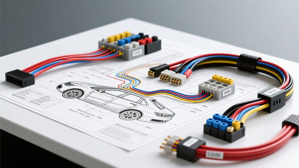
The Intersection of Heavy-Duty Chassis and Agricultural Irrigation
Integrating skid-mounted sprayers, PTO-driven water pumps, and electric solenoid manifolds into heavy-duty trucks and agricultural tractors requires a deep understanding of both automotive electrical architecture and high-draw fluid dynamics. Whether you are outfitting a Ford F-550 with a rear-mounted fertilizer sprayer or wiring a John Deere tractor for a pivoting irrigation setup, the electrical demands are severe. Reviewing a standard wiring diagram for irrigation system components is only the first step; adapting those diagrams to survive the harsh, high-vibration, and wet environments of a vehicle chassis is where most installations fail.
At Autoflowwire, we frequently diagnose catastrophic electrical fires and destroyed Body Control Modules (BCMs) resulting from improper agricultural upfitting. This guide outlines the critical safety warnings, common wiring mistakes, and exact specifications required to safely integrate irrigation systems into modern vehicle platforms.
Critical Safety Warnings Before Tapping the Chassis
The CAN-Bus Backfeed Hazard
Modern heavy-duty trucks (2015-present) utilize multiplexed Controller Area Network (CAN-bus) systems. A fatal mistake made by amateur upfitters is tapping into existing chassis lighting circuits—such as the reverse lights or running lamps—to provide a 12V trigger signal for an irrigation pump relay. These circuits are not simple 12V feeds; they are pulse-width modulated (PWM) signals monitored by the BCM. Backfeeding 12V from an aftermarket irrigation switch into a BCM-monitored tail light circuit will instantly fry the module, resulting in a $2,500+ replacement cost and a disabled vehicle.
Safety Directive: Always use a dedicated Upfitter switch circuit or an isolated PTO (Power Take-Off) relay block. For Ford Super Duty trucks, consult the Ford Truck Body Builder Advisory Service (BBAS) to locate the dedicated upfitter relay outputs in the engine bay, which are completely isolated from the CAN-bus network.
Alternator Overload and Inrush Current Miscalculations
Electric irrigation pumps, particularly 12V DC diaphragm and centrifugal pumps, exhibit massive inrush currents. A pump rated for 30 amps continuous may draw 120 amps for the first 400 milliseconds during startup. If your wiring diagram does not account for this inrush spike using the correct slow-blow fusing and heavy-gauge wiring, the voltage drop across the chassis will starve the vehicle's Engine Control Unit (ECU), causing the engine to stall exactly when the irrigation system is engaged.
Common Wiring Mistakes in Truck-Mounted Irrigation
- Using Household/THHN Wire: Stranded automotive wire (SGT or GXL) is required. Solid core THHN wire will fracture within weeks due to chassis vibration.
- Ignoring Flyback Diodes: Irrigation solenoid valves are inductive loads. When the circuit opens, the collapsing magnetic field generates a high-voltage spike (back-EMF) that can exceed 100V. Without a flyback diode wired in parallel with the solenoid, this spike will arc across the relay contacts or destroy the switching transistor in an automated GPS rate controller.
- Undersized Ground Paths: Relying on the truck bed or trailer hitch for a ground return. The bed-to-chassis ground strap is typically 10 AWG and cannot handle a 40A irrigation pump return. You must run a dedicated 4 AWG ground wire directly from the pump motor to the negative battery terminal.
Correct Wiring Diagram Specifications for Pump and Solenoids
When drafting or modifying your wiring diagram for irrigation system integration on a long-wheelbase truck, voltage drop is your primary enemy. A 30-foot run of wire requires a larger gauge than a 5-foot run to deliver the same amperage to the rear-mounted pump. Below is the strict specification chart for a standard 12V truck-mounted irrigation manifold.
| Circuit Application | Wire Gauge (AWG) | Insulation Type | Wire Color Code | Fusing & Protection |
|---|---|---|---|---|
| Main Pump Power Feed (Battery to Relay) | 4 AWG | SGT / XHHW-2 | Red | 150A Mega Fuse (within 18" of battery) |
| Pump Relay to Motor | 8 AWG | GXL (High Temp) | Red with White Stripe | 50A MAXI Fuse at relay output |
| Solenoid Valve Manifold (Up to 6 Zones) | 14 AWG | GXL | Yellow (Trigger), Black (Common) | 15A ATO Fuse, Flyback Diodes required |
| PTO / Upfitter Trigger Signal | 16 AWG | GXL | Blue | 5A Tap-a-Circuit or Upfitter Block |
| Main System Ground Return | 4 AWG | SGT | Black | Ring terminal, anti-oxidant paste |
Connector Selection for Wet and Dusty Environments
Irrigation environments guarantee exposure to water, corrosive fertilizers, and fine silt. Standard PVC electrical tape and heat-shrink butt splices will fail, allowing moisture to wick into the copper strands via capillary action, leading to copper sulfation (the green crust that causes high-resistance voltage drops).
According to TE Connectivity's automotive connector specifications, you must use environmentally sealed connectors rated to IP68 or IP69K. The Deutsch DT series is the industry standard for agricultural wiring. When crimping Deutsch pins, you must use the proper pneumatic or manual ratcheting crimper to ensure the wire barrel compresses exactly to the AWG spec without cutting the copper strands. Furthermore, always apply dielectric grease to the mating faces of the connector to prevent fertilizer salts from bridging the pins and causing parasitic draws.
Troubleshooting Decision Tree: Irrigation Electrical Faults
When the irrigation system fails to engage or causes vehicle electrical anomalies, follow this diagnostic sequence before replacing components.
Symptom 1: Pump Hums but Fails to Build Pressure / Engine Stalls
- Check Voltage at Pump Terminals: Set multimeter to DC Volts. Engage pump. If voltage reads below 10.5V, you have a severe voltage drop.
- Perform Voltage Drop Test: Measure voltage across the positive cable, then across the ground cable while the circuit is under load. A drop greater than 0.2V per connection indicates a corroded terminal or undersized wire.
- Verify Alternator Output: If the truck's alternator is rated for 150A and the base vehicle draw is 120A, adding a 40A irrigation pump will overload the system. Upgrade to a high-output 220A+ alternator.
Symptom 2: GPS Rate Controller Reboots When Solenoids Fire
- Inspect for Back-EMF: This is caused by missing or blown flyback diodes on the solenoid valves.
- Test Diodes: Disconnect the solenoid harness. Use the multimeter's diode test mode. Place the red probe on the cathode (banded end) and black on the anode. It should read OL (Open Loop). Reverse probes; it should read 0.4V to 0.7V. If it reads shorted or open in both directions, replace the diode immediately to save the rate controller.
Symptom 3: BCM Throws 'Trailer Wiring Fault' Code
- Identify the Parasitic Tap: Someone has likely spliced the irrigation trigger wire into the truck's 7-way trailer plug circuit to use the cab's trailer brake controller switch as a pump trigger.
- Corrective Action: Remove the scotch-lock splice. Reroute the trigger wire to an isolated upfitter relay block, referencing the SAE J1128 standard for proper wire routing away from high-heat exhaust components and sharp chassis edges.
Final Safety Directives
Wiring an irrigation system to a vehicle is not a simple household electrical project. The combination of high inrush currents, inductive spikes, and corrosive environments demands strict adherence to automotive-grade standards. Always use GXL/SGT cross-linked polyethylene insulated wire, seal all connections with IP68-rated connectors, and isolate your high-draw pump circuits from the vehicle's sensitive CAN-bus data networks. By following these specifications, your truck-mounted or PTO-driven irrigation system will operate reliably for years without compromising the vehicle's core electrical architecture.