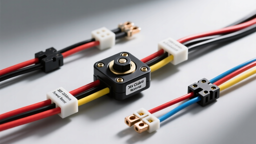
Understanding the 36V Club Car F&R Architecture
The Forward and Reverse (F&R) switch on a 36V Club Car DS is one of the most frequently serviced, yet fundamentally misunderstood, components in the golf cart electrical system. Whether you are working on a classic 36V Series (resistor/coil) model or a later 36V SepEx (Separately Excited) regenerative model, the F&R assembly dictates the directional logic of the drive motor. On older 36V Series vehicles, the F&R switch is a heavy-duty mechanical drum or contactor that physically routes high-amperage DC current to reverse the motor's polarity. On later models, the mechanical lever simply actuates low-current microswitches that send 12V-16V logic signals to the motor controller.
Misinterpreting the 36v club car forward reverse switch wiring diagram is a primary cause of melted busbars, fried controllers, and catastrophic motor runaway. This guide dissects the exact wiring schematics, outlines the most common installation mistakes, and provides critical safety protocols for working on 36V DC high-current systems.
The Anatomy of the 36V F&R Wiring Circuit
Before turning a wrench, it is vital to understand how the F&R switch interfaces with the main solenoid, the speed controller, and the drive motor. In a standard 36V Club Car DS Series configuration, the F&R switch sits between the main battery pack positive feed and the motor's armature/field coils.
- Main Power Input (B+): Receives 36V DC directly from the battery pack via the main solenoid or key switch.
- Motor Outputs: Routes the 36V DC to either the Armature (A1) or the Field (S1) depending on the lever position.
- Microswitch Triggers: The physical lever simultaneously depresses a directional microswitch (completing the solenoid trigger circuit) and a neutral safety switch (preventing the cart from starting in gear).
- Reverse Buzzer Circuit: A secondary microswitch completes a ground path for the reverse warning alarm when the lever is pulled backward.
Top 5 Catastrophic Wiring Mistakes
When referencing a wiring schematic, even a single crossed wire can result in thousands of dollars in damage. Below are the most common errors technicians and DIYers make when wiring the 36V F&R switch.
1. Reversing Both Armature and Field Leads
The rotational direction of a DC series motor is determined by the relative magnetic polarity between the armature and the stator field. To reverse the motor, you must reverse the current flow through either the armature or the field, but never both. A common mistake when rebuilding a 36V F&R switch is swapping both the A1/A2 and S1/S2 cables at the switch terminals. Because both magnetic fields reverse simultaneously, their relative polarity remains identical. The result? The cart drives forward in both the Forward and Reverse positions. Always verify your motor lead routing against the OEM schematic before applying power.
2. Using Undersized AWG for High-Current Lugs
The main F&R terminals on a 36V Series cart carry the full amperage load of the drive motor, which can spike beyond 300 amps under heavy load or hill climbs. According to SAE J1128 standards for low-tension primary battery cables, high-current DC routing requires a minimum of 2 AWG or 4 AWG copper wire. Many DIYers mistakenly use 6 AWG wire because it is easier to route through the frame. This undersized wire creates severe voltage drop and resistance, generating enough heat to melt the F&R switch's internal copper busbars and plastic housing.
3. Omitting Flyback Diodes on Solenoid Coils
When the F&R microswitch opens, the collapsing magnetic field of the main solenoid coil generates a massive inductive voltage spike (back-EMF). If flyback suppression diodes are not installed across the solenoid coil terminals, this spike travels backward through the microswitch wiring, instantly vaporizing the delicate internal contacts of the F&R directional microswitches. Always ensure a 1N5408 (or equivalent) diode is soldered across the solenoid coil, with the cathode stripe facing the positive terminal.
4. Misaligning the Neutral Safety Microswitch
The F&R assembly features a neutral safety microswitch designed to break the solenoid trigger circuit when the lever is in the center 'Neutral' detent. If the switch is misaligned during reassembly, the cart may lurch forward or backward the moment the key is turned, bypassing the pedal safety interlock. The microswitch roller must sit precisely in the detent groove, requiring a feeler gauge check to ensure a 0.020-inch clearance before the switch clicks.
5. Over-Torquing Microswitch Spade Terminals
While the main high-current battery lugs require significant torque, the 14 AWG to 16 AWG wires connected to the F&R microswitches use standard 1/4-inch spade connectors. Applying excessive force with pliers to secure these spades often cracks the bakelite housing of the microswitch, leading to internal arcing and premature failure. Use a dedicated crimping tool and apply no more than 15 in-lbs of torque on the mounting screws.
F&R Terminal & Wire Color Reference Chart
The following table outlines the standard terminal designations, wire colors, and specifications for a classic 36V Club Car DS Series F&R switch and associated microswitches. Note that aftermarket harnesses may deviate from OEM colors; always trace the circuit to verify.
| Terminal / Component | Function | OEM Wire Color | AWG Size | Torque Spec |
|---|---|---|---|---|
| F&R Main Post 1 (Input) | B+ from Main Solenoid | Red | 2 AWG | 15 ft-lbs |
| F&R Main Post 2 | Output to Motor Armature (A1) | Blue | 2 AWG | 15 ft-lbs |
| F&R Main Post 3 | Output to Motor Field (S1) | Yellow | 2 AWG | 15 ft-lbs |
| F&R Main Post 4 | Motor Return / Controller B- | Black | 2 AWG | 15 ft-lbs |
| Fwd Microswitch (COM) | 12V/16V Trigger Input | Red (14 AWG) | 14 AWG | 10 in-lbs |
| Fwd Microswitch (NO) | Solenoid Coil Trigger Out | Blue/White | 14 AWG | 10 in-lbs |
| Rev Buzzer Microswitch | Ground Trigger for Alarm | Pink / Orange | 16 AWG | 10 in-lbs |
Critical Safety Warnings for 36V DC Systems
Working on a 36V DC golf cart battery bank presents severe electrical hazards that are often underestimated by hobbyists. DC current does not cross zero like AC current, meaning an arc flash sustained by a 36V battery bank will not self-extinguish and can easily cause severe burns or ignite surrounding plastics.
- Lockout/Tagout Protocol: Before touching any F&R terminal, disconnect the main negative battery cable from the battery pack. Never rely solely on the key switch or the tow/run switch to isolate power.
- Capacitor Discharge: If your 36V system utilizes an electronic speed controller, the internal capacitors can hold a lethal charge even after the batteries are disconnected. Turn the key to the 'ON' position and press the accelerator pedal for 10 seconds after disconnecting the main battery negative to safely bleed off residual capacitor voltage.
- Series Motor Runaway Risk: Never test a 36V Series motor on a bench without a mechanical load or a dyno. If the field coil wiring is compromised or the F&R switch is wired incorrectly, a Series motor can experience a 'runaway' condition, spinning beyond 10,000 RPM until the armature physically explodes from centrifugal force.
- Corrosion Mitigation: 36V battery banks vent sulfuric acid gas, which rapidly corrodes copper lugs. After torquing the F&R switch lugs, coat the terminals with a dielectric grease or a dedicated battery terminal protector spray to prevent micro-arcing caused by copper oxide buildup.
F&R Circuit Troubleshooting Decision Tree
When the cart fails to move or moves in the wrong direction, use this logical diagnostic tree to isolate the fault within the F&R circuit. For comprehensive schematics and community-tested bypass diagrams, resources like Golf Cart Garage wiring archives provide excellent visual references.
Symptom: Cart only moves Forward, regardless of F&R lever position.
- Check: Are both Armature and Field leads swapped at the motor or F&R switch?
- Fix: Swap either the A1/A2 leads OR the S1/S2 leads. Do not swap both.
- Check: Is the F&R mechanical drum internally welded or fused in the Forward position due to heat damage?
- Fix: Disassemble the switch housing and inspect the copper contacts. Replace the entire F&R assembly if pitting exceeds 1mm.
Symptom: Cart moves in Reverse, but the reverse buzzer does not sound.
- Check: Is the 16 AWG Pink/Orange wire securely seated on the reverse microswitch spade?
- Fix: Re-crimp the spade connector and ensure the microswitch roller is making full contact with the lever cam.
- Check: Is the buzzer ground path intact?
- Fix: Test the buzzer directly with a 12V source. If functional, trace the ground wire back to the chassis or controller ground bus.
Symptom: Cart is completely dead in both Forward and Reverse (No solenoid click).
- Check: Is the neutral safety microswitch out of alignment?
- Fix: Adjust the microswitch mounting bracket until you hear a distinct 'click' when shifting into the detents.
- Check: Has the flyback diode failed, allowing back-EMF to melt the internal contacts of the directional microswitches?
- Fix: Test microswitch continuity with a multimeter. Replace the microswitches and install a new suppression diode across the main solenoid coil.
By strictly adhering to the correct wire gauges, respecting the physics of DC motor polarity, and following rigorous safety protocols, you can ensure your 36V Club Car F&R system operates reliably for years. Always verify your specific model year's schematic, as minor variations exist between early resistor models and later solid-state controller configurations.