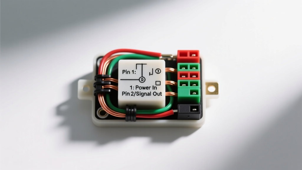
Introduction to the 2 Pin Flasher Relay Wiring Diagram Manual
Whether you are restoring a classic muscle car, wiring a custom motorcycle, or troubleshooting a faulty turn signal circuit on an older daily driver, understanding your flasher unit is critical. This 2 pin flasher relay wiring diagram manual is designed specifically for beginners who want to grasp the fundamentals of automotive lighting circuits without getting lost in overly complex OEM schematics. A 2-pin flasher is the most basic, widely used electromechanical or electronic switching device for controlling turn signals and hazard lights. By the end of this guide, you will understand exactly how to wire, test, and upgrade your flasher relay using proper AWG wire sizes, standard color codes, and safe circuit protection methods.
How a 2-Pin Flasher Relay Works: The Fundamentals
Unlike a standard 4-pin or 5-pin automotive relay that uses a low-current trigger to switch a high-current load, a flasher relay is a self-contained timing and switching device. It sits directly in series with the lighting circuit. When you activate your turn signal switch, current flows from the battery, through the fuse, into the flasher relay, and out to the bulbs. The relay interrupts this current at a specific rate (typically 60 to 120 flashes per minute, per SAE J589 standards) to create the blinking effect.
Because it is a series circuit, the flasher relay relies on the electrical load (the resistance of the light bulbs) to function correctly. This is a crucial concept for beginners: if a bulb burns out, the circuit resistance changes, which drastically alters the flashing speed or stops it entirely.
Understanding the 2 Pin Flasher Relay Pinout
The physical flasher unit will have two male spade terminals. While they may look identical, they serve distinctly different purposes. Wiring them backward on certain electronic units can cause circuit failure, though older thermal units are often bi-directional. Always check the casing for stamped letters.
| Terminal Pin | Designation | Function & Connection | Current Flow |
|---|---|---|---|
| B | Battery / Power | Receives 12V+ from the ignition switch (turn signals) or directly from the battery via a fuse block (hazard lights). | Input (Source) |
| L | Load / Lamp | Outputs the pulsed 12V+ to the turn signal switch, which then routes power to the left or right corner bulbs. | Output (Load) |
Step-by-Step Wiring Guide for Beginners
Follow these foundational steps to wire a 2-pin flasher relay safely and effectively. For deeper insights into automotive circuit protection, refer to Haynes Automotive Electrical Basics.
Step 1: Establish a Fused Power Source
Never wire a flasher relay directly to an unfused battery terminal. You must connect the B (Battery) pin to a switched 12V+ source (if used only for turn signals) or a constant 12V+ source (if used for hazard lights). This wire must be protected by an inline fuse or routed through a fuse block. A 10A or 15A fuse is standard for a 2-bulb or 4-bulb incandescent lighting circuit.
Step 2: Connect the Load Output
Connect the L (Load) pin to the common input terminal of your turn signal switch or hazard switch. This wire will carry the pulsed voltage to the switch, which acts as a manual router to send power to either the left or right side of the vehicle.
Step 3: Grounding the Bulbs (Not the Relay)
A common beginner mistake is looking for a ground wire on a 2-pin flasher. There is no ground pin on a 2-pin relay. The circuit completes its path to ground at the light bulb sockets. Ensure your tail light and front marker housings have clean, bare-metal grounding points to the vehicle chassis to prevent dim lights or back-feeding.
Wire Gauge (AWG) and Color Code Specifications
Using the correct wire gauge prevents voltage drop and melted insulation. Automotive lighting circuits draw moderate current, but the main feed must handle the combined load of all active bulbs. Standard incandescent turn signal bulbs (e.g., 1156 or 1157) draw roughly 2.1 Amps each. Four bulbs equal 8.4 Amps.
| Circuit Segment | Recommended AWG | Standard Custom/Aftermarket Color | OEM Color (Typical GM/Ford) |
|---|---|---|---|
| Fuse Block to Pin B (Power) | 14 AWG | Red | Purple or Light Blue |
| Pin L to Turn Signal Switch | 16 AWG | Yellow or Light Green | Brown or Light Green |
| Switch to Left Corner Bulbs | 18 AWG | Yellow | Yellow |
| Switch to Right Corner Bulbs | 18 AWG | Green | Green |
| Dash Indicator Light | 20 AWG | Blue or White | Varies |
Thermal vs. Electronic Flashers: Why Your Bulbs Matter
When utilizing this 2 pin flasher relay wiring diagram manual, you must decide between a thermal and an electronic flasher unit. This choice dictates what type of bulbs you can use.
- Thermal Flashers (Electromechanical): These use a bimetallic strip that heats up and bends to break the circuit, then cools and reconnects. They are load-dependent. If you swap to low-wattage LED bulbs, the strip will not heat up, and the lights will either stay solid or flash incredibly fast (hyperflashing).
- Electronic Flashers (Solid State): These use an integrated circuit (IC) and a MOSFET to time the flashes. They are often load-independent (labeled as "LED Compatible" or "No Load Required"). If you are upgrading a classic car to LEDs, an electronic 2-pin flasher is mandatory unless you plan to wire bulky 6-ohm, 50W load resistors in parallel with every LED bulb.
Troubleshooting Common Flasher Relay Issues
Even with a perfect wiring diagram, real-world automotive environments introduce corrosion, bad grounds, and failing components. Use this diagnostic tree to solve common issues:
Symptom 1: Turn Signals Stay Solid (No Flashing)
- Cause A: Burnt out bulb on the active side. (The circuit lacks the resistance/current to trigger the thermal strip). Fix: Replace bulb.
- Cause B: Installed LED bulbs with a thermal flasher. Fix: Upgrade to an electronic LED-compatible flasher or install load resistors.
- Cause C: Short to ground on the L (Load) wire before the switch. Fix: Inspect wiring harness for pinched insulation.
Symptom 2: Hyperflashing (Flashing Too Fast)
- Cause: Reduced circuit load. The flasher unit interprets the lower current draw as a burnt-out bulb (a built-in safety warning feature). Fix: Check for blown bulbs or upgrade to an adjustable electronic flasher relay.
Symptom 3: Dash Indicator Light Stays On, But Corners Do Not Flash
- Cause: Bad ground at the corner bulb sockets. The dash indicator is back-feeding through the filament of the ungrounded corner bulbs. Fix: Sand the socket housings and apply dielectric grease.
Testing the Circuit with a Digital Multimeter
To verify your wiring before connecting expensive LED taillights, use a digital multimeter (DMM) set to DC Volts.
- Turn the ignition to the "ON" position (or activate the hazard switch).
- Probe the B terminal wire. You should read a steady 12.0V to 12.6V. If you read 0V, check your fuse and ignition switch.
- Probe the L terminal wire while the turn signal switch is engaged. The multimeter should pulse between 0V and 12V in a rhythmic cadence.
- If the L terminal shows a steady 12V but no pulsing, the internal mechanism of the flasher relay has failed and the unit must be replaced.
Authoritative References & Further Reading
For advanced diagnostics and OEM-specific wiring variations, consult the following resources:
- SAE J589: Turn Signal Lamps Standard - Defines the legal flash rates and candela requirements for automotive turn signals.
- Haynes Automotive Electrical Basics - Excellent foundational reading on multimeter usage and circuit tracing.
- Delphi Technologies Technical Resources - Manufacturer insights on solid-state relay degradation and thermal management in automotive lighting modules.