The Foundation: Sourcing Accurate Chevrolet Wiring Diagrams
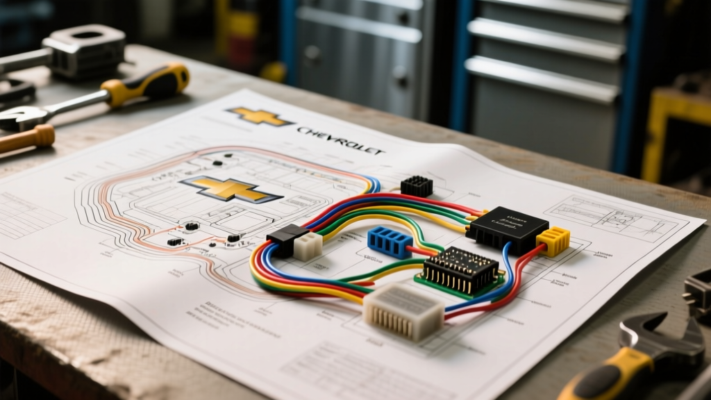
Executing a flawless Gen III or Gen IV LS engine swap into a classic Chevy chassis, hot rod, or non-native platform requires more than just motor mounts and an oil pan. The true bottleneck of any LS swap project is the electrical integration. Relying on generic forum advice often leads to melted harnesses, parasitic draws, and erratic sensor readings. To perform a professional-grade harness reduction and integration, you must learn to navigate factory Chevrolet wiring diagrams. These OEM schematics provide the exact circuit routing, wire gauge specifications, and splice pack locations necessary to safely strip the factory engine harness of its modern emissions bloat while retaining the critical powertrain control functions.
When sourcing diagrams, avoid third-party wiki sites. Instead, utilize factory GM Service Information (often available via Helm Incorporated) or dedicated SAE standard documentation for wire insulation types. Understanding the difference between a chassis harness, an engine harness, and a dash integration module (DIM) is critical before you pick up your wire strippers.
PCM Connector Identification and Pinout Strategy
The 1999-2006 LS1, LM7 (5.3L), and LQ4 (6.0L) engines utilize the P01 or P59 Powertrain Control Module (PCM). These computers feature three distinct 80-way Delphi connectors, color-coded for identification. When modifying your harness, you will primarily interact with the C1 (Blue) and C2 (Red) connectors. The C3 (Gray) connector is largely dedicated to transmission control (TCC, shift solenoids) and secondary emissions, making it a prime candidate for complete removal in manual transmission swap projects.
Below is a reference table for the most critical circuits located on the C1 (Blue) connector that must be retained and properly routed through your firewall during a standalone engine swap.
| PCM Pin | Wire Color | Circuit Name / Function | Modification Notes |
|---|---|---|---|
| C1-10 | Dark Green | Tachometer Output | Connect to aftermarket tach; requires a pull-up resistor or signal converter for older analog gauges. |
| C1-20 | Pink | Ignition 12V Feed | Must be switched 12V. Do not connect to constant battery power or the PCM will remain awake, draining the battery. |
| C1-57 | Pink/Black | Fuel Pump Relay Control | Provides a ground path to trigger the fuel pump relay. Prime cycle is 2 seconds upon key-on. |
| C1-68 | Light Blue/Black | Vehicle Speed Sensor (VSS) | Crucial for drive-by-wire idle control and speedometer output. Requires 4,000 PPM signal from transmission tailshaft. |
| C1-79 | Orange | Battery 12V Feed (Keep Alive) | Constant 12V. Requires an inline 15A Maxi fuse placed within 6 inches of the battery terminal. |
Harness Reduction: Deleting Emissions and VATS
A factory LM7 truck harness is wrapped in split-loom and electrical tape, containing dozens of wires for EVAP purges, secondary air injection, and rear oxygen sensors. When utilizing Chevrolet wiring diagrams to reduce the harness, your goal is to extract only the injectors, coil packs, front O2 sensors, MAP, IAT, TPS, and MAF sensors.
The VATS Bypass Dilemma
The Vehicle Anti-Theft System (VATS) will disable the fuel injectors if the PCM does not receive the correct resistance signal from the ignition key cylinder. While you can wire a 523-ohm resistor into the VATS circuit (typically the White and White/Black wires on the C2 connector), the professional modification route is to have the PCM flashed to disable VATS entirely. This removes two points of failure and simplifies your under-dash wiring.
Rear O2 and EVAP Deletion
Cut the Dark Green (EVAP purge solenoid) and Brown/White (EVAP vent solenoid) wires flush at the PCM plug. Extract the pins from the Delphi connector using a proper terminal release tool (Delphi part #12094429) to maintain the weather-seal integrity of the connector. Never simply cut wires and leave them dangling inside the loom; capillary action will wick moisture directly into the PCM.
Heavy Gauge Upgrades for Fuel and Charging Systems
Factory Chevrolet wiring diagrams specify wire gauges based on the exact electrical load of the original vehicle. When swapping an LS into a classic car with a high-amp aftermarket fuel pump (e.g., Walbro 450 or Aeromotive 340) and a 140A+ alternator, the factory 10 AWG and 12 AWG wiring is dangerously undersized. Upgrading these circuits prevents voltage drop, which can cause the PCM to misread sensor data and pull timing under heavy load.
| Circuit | Factory AWG | Recommended Swap AWG | Wire Type Specification |
|---|---|---|---|
| Alternator Main Output | 10 AWG | 4 AWG or 2 AWG | SAE J1128 GXL Cross-Linked Polyethylene |
| Fuel Pump Feed (Relay to Pump) | 14 AWG | 10 AWG | TXL High-Temp Automotive Wire |
| Fuel Pump Ground | 14 AWG | 10 AWG | TXL High-Temp Automotive Wire |
| PCM Main Power Feed | 14 AWG | 12 AWG | GXL Cross-Linked Polyethylene |
Always use SAE-approved GXL or TXL wire for under-hood applications. Standard THHN wire from a hardware store has PVC insulation that becomes brittle and melts when exposed to exhaust manifold radiant heat. For terminations, abandon crimp-and-solder methods in high-vibration zones; use adhesive-lined heat shrink crimps with Delphi Metri-Pack 150 or 280 series terminals to match the OEM connections.
Critical Grounding Protocols for Swapped LS Engines
The most common cause of erratic idle, misfires, and blown PCM drivers in LS swaps is inadequate grounding. According to SAE electrical standards and GM factory service protocols, the PCM relies on ultra-clean, zero-resistance ground paths to accurately read millivolt signals from the MAF and O2 sensors.
- Engine Block to Chassis: Use a minimum 4 AWG braided copper grounding strap connecting the passenger side cylinder head or engine block to the chassis. Torque the block bolt to 15 lb-ft.
- PCM Grounds: The P01/P59 PCM grounds are located at the rear of the cylinder heads. You must remove the paint, powder coating, or rust from the grounding surface. Use a star washer and an M8 bolt, torqued to 15 lb-ft. Do not use threadlocker on ground bolts, as it acts as an electrical insulator.
- Cylinder Head Grounds: Ensure the factory ground wires running from the rear of the heads to the firewall or frame are intact. If deleted during the harness strip-down, the PCM will experience floating grounds, leading to random injector pulse failures.
Troubleshooting Common Swap Electrical Gremlins
Even with perfect adherence to Chevrolet wiring diagrams, swap projects often present unique electrical anomalies. Here is a diagnostic decision tree for common issues:
Symptom: Engine Cranks but No Injector Pulse
- Verify 12V at the Pink wire (Pin 20, C1) during cranking.
- Check the 58X crankshaft position sensor wiring. The CKP sensor uses a shielded cable; ensure the shield drain wire is grounded ONLY at the PCM end to prevent electromagnetic interference (EMI) from the starter motor.
- Confirm VATS is disabled in the PCM tune or physically bypassed.
Symptom: Tachometer Bouncing or Reading Zero
The factory LS PCM outputs a 5V square wave tach signal on the Dark Green wire (Pin 10, C1). Classic Chevy dash gauges expect a 12V negative-edge trigger signal from a traditional HEI distributor. You must install a tach signal converter (such as the Dakota Digital SGI-5C) to step up the voltage and adjust the pulse rate to match your gauge cluster's expectations.
Symptom: Alternator Not Charging (L-Terminal Issue)
The CS130D and AD244 alternators require a 12V excitation signal on the 'L' terminal to begin charging. In a standalone harness, this is typically fed from the PCM (Gray wire, Pin 55 on C2) or a switched ignition source via a 100-ohm, 1/2-watt resistor. If the alternator whines or fails to charge above 12.4V, check for voltage drop across this excitation circuit.
Mastering the factory schematics is the difference between a swap that runs flawlessly for 100,000 miles and one that leaves you stranded on the side of the road. Invest in the proper terminal tools, use cross-linked automotive wire, and respect the OEM pinout data. For further reading on connector standards, refer to the Delphi Automotive Connection Systems catalog to ensure your weather-pack seals are correctly seated.