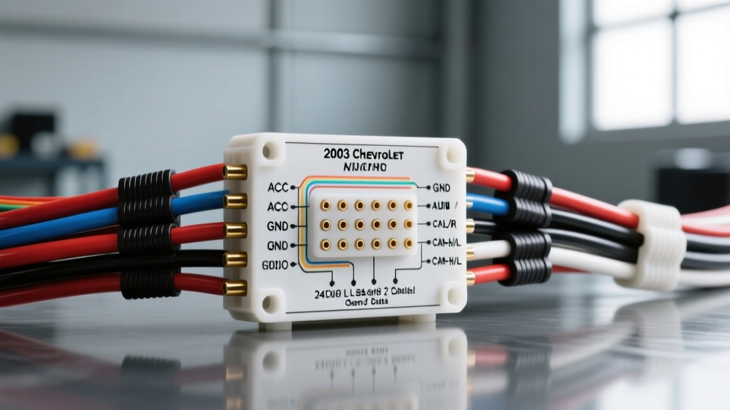
GMT800 Audio Architecture Overview
The 2003 Chevrolet Tahoe, part of the GMT800 platform generation, introduced significant complexities to the vehicle's audio and electrical architecture. Unlike the simpler 1995-2002 C/K and early GMT800 trucks, the 2003 model year fully integrated the radio into the vehicle's Body Control Module (BCM) network via the Class 2 serial data bus. This means that accessing a basic 2003 Tahoe stereo wiring diagram is only the first step; understanding the data-driven Retained Accessory Power (RAP) and Theftlock systems is critical for any aftermarket head unit installation or OEM diagnostic procedure.
This technical reference provides the exact Delphi Packard 24-pin connector pinout, OEM wire color codes, AWG specifications, and diagnostic procedures required to properly interface with the 2003 Tahoe's audio system. Whether you are bypassing a factory Bose amplifier, integrating an OnStar retention module, or diagnosing a parasitic draw, the specifications below serve as your definitive guide.
Main 24-Pin Radio Harness Pinout Specifications
The 2003 Tahoe utilizes a primary 24-pin Delphi Packard connector for power, ground, illumination, and high-level speaker outputs (on base audio models). Below is the standardized OEM pinout configuration. Note that wire colors are standardized, but cavity positions may shift slightly depending on whether the vehicle is equipped with the base RPO UQ3 or the premium Bose RPO UQ4 system.
| Pin / Cavity | Function | OEM Wire Color | AWG |
|---|---|---|---|
| A1 | Left Rear Speaker (+) | Brown | 18 |
| A2 | Left Rear Speaker (-) | Brown/White | 18 |
| A3 | Right Rear Speaker (+) | Dark Blue | 18 |
| A4 | Right Rear Speaker (-) | Dark Blue/White | 18 |
| A5 | Right Front Speaker (+) | Light Green | 18 |
| A6 | Right Front Speaker (-) | Dark Green | 18 |
| A7 | Left Front Speaker (+) | Tan | 18 |
| A8 | Left Front Speaker (-) | Gray | 18 |
| A9 | Amplifier Remote Turn-On | Brown/White | 20 |
| A10 | Illumination (Park Lamp) | Orange/White | 22 |
| A11 | Dimmer Signal | Gray | 22 |
| A12 | Switched 12V (Ignition/RUN) | Brown | 14 |
| A13 | Constant 12V (Battery) | Yellow | 14 |
| A14 | Chassis Ground | Black/White | 14 |
| A15 | Class 2 Serial Data Bus | Light Green | 22 |
Power, Ground, and RAP Circuit Logic
The most common failure point in aftermarket installations on the 2003 Tahoe is the mismanagement of the Switched 12V (Brown, Pin A12) and the Class 2 Data line (Light Green, Pin A15). In the GMT800 architecture, the BCM controls Retained Accessory Power (RAP). When the ignition is turned off, the BCM continues to supply power to the radio circuit until a door is opened, or a 10-minute timeout expires.
If you are wiring an aftermarket head unit directly to the Brown wire without a CAN-bus/Class 2 interface module (such as the Axxess ASWC-1 or GMOS-01), the radio will shut off immediately when the key is turned to the OFF position, losing the RAP functionality. Furthermore, the Yellow constant 12V wire (Pin A13) is responsible for maintaining the radio's volatile memory and providing the primary current path during high-volume transient peaks. Ensure the Yellow wire is connected to a dedicated 15A fused circuit if the aftermarket head unit features an internal 4x50W amplifier, as the OEM 14 AWG wiring may experience voltage drop under heavy subwoofer load.
Class 2 Serial Data & Anti-Theft Integration
The Light Green wire (Pin A15) is the backbone of the 2003 Tahoe's audio security and chime integration. Operating on the SAE J1850 VPW (Variable Pulse Width) standard, the Class 2 serial data bus transmits messages at 10.4 kbps. This single wire handles three critical functions:
- Theftlock (VIN Matching): The radio continuously polls the BCM for the vehicle's VIN. If the radio is swapped from another 2003+ GM vehicle without being flashed with the correct VIN via a GM MDI or Tech 2 scanner, the display will read "LOC" or "LOCKED" and disable all audio output.
- Chime Integration: The factory radio acts as the amplifier for the BCM's warning chimes (seatbelt, door ajar, turn signals). Bypassing the Class 2 line without a chime retention module will result in the loss of all audible vehicle warnings, which is a critical safety hazard.
- OnStar Audio Muting: The Class 2 bus signals the radio to mute the audio channels and route the OnStar microphone signal through the front speakers during an active cellular call.
Bose Amplifier and OnStar Bypass Wiring
If your 2003 Tahoe is equipped with the premium Bose audio system (RPO UQ4), the factory head unit does not output high-level speaker signals. Instead, it outputs low-level, differential, floating-ground audio signals to the factory Bose amplifier, typically located under the center console or behind the rear trim panel. Connecting standard high-level aftermarket speaker wires directly to a Bose factory harness will result in severe audio distortion, blown tweeters, or a dead short that can damage the aftermarket head unit's internal IC.
To properly bypass the Bose amplifier while retaining OnStar and steering wheel controls, you must use a dedicated line-output converter (LOC) or a digital interface module like the Metra GMOS-01. This module intercepts the Class 2 data line, generates a simulated 12V remote turn-on signal, translates the low-level Bose outputs to standard RCA pre-outs, and generates a localized square-wave chime to replace the factory BCM chimes.
Multimeter Diagnostics for the 24-Pin Connector
When diagnosing a dead radio or a parasitic battery draw originating from the audio circuit, use a digital multimeter (DMM) to verify the following at the back of the 24-pin Delphi connector:
- Constant 12V (Yellow): Should read 12.2V - 12.6V with the vehicle off. If reading below 11.5V, check the 15A "RDO" fuse in the underhood fuse block and inspect for corrosion at the battery junction block.
- Ground (Black/White): Perform a voltage drop test between Pin A14 and the vehicle's bare chassis. A reading higher than 0.05V indicates a poor ground connection, which will cause the radio to reboot when the bass hits or the interior lights dim.
- Class 2 Data (Light Green): Set your DMM to DC Voltage. With the ignition ON, the Light Green wire should read a pulsing DC voltage averaging between 6.5V and 7.5V. If the line reads a solid 0V or a solid 12V, the Class 2 bus is either shorted to ground or shorted to power, effectively taking down the entire BCM communication network. For precise diagnostics, an oscilloscope should show a clean 0-7V square wave.
Authoritative References
For advanced diagnostics and module flashing procedures, refer to the following industry standards and manufacturer resources:
- SAE International - J1850 Class B Data Communication Network Interface (Detailed specifications on the VPW protocol utilized by GM's Class 2 serial data bus).
- Metra Electronics - GMT800 Integration Harness Specifications (Wiring schematics and pinout verifications for 2003-2006 GM truck radio adapters).
- Crutchfield Vehicle Fitment Database (Comprehensive OEM audio configurations, Bose bypass requirements, and steering wheel control integration data for the 2003 Chevrolet Tahoe).