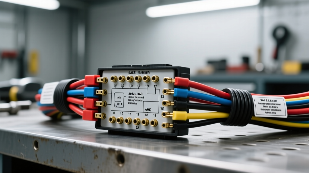
Understanding the SAE J560 Standard for Class 8 Vehicles
Consulting an accurate semi truck plug wiring diagram is the first step in preventing catastrophic electrical failures on the highway. For Class 8 semi-trucks and heavy-duty commercial trailers, the universal standard governing the electrical connection between the tractor and the trailer is the SAE J560 7-way connector. Unlike standard 4-way or 7-way RV connectors found on light-duty pickups, the commercial semi truck plug is engineered to handle higher continuous amperage loads, harsh environmental exposure, and the intense vibration profiles inherent to heavy-haul trucking.
Despite the standardized nature of the SAE J560 specification, electrical gremlins remain one of the top three causes of roadside breakdowns and DOT citations. Misinterpreting a wiring schematic, using undersized wire gauges, or ignoring proper crimping protocols can lead to melted housings, trailer brake failures, and dangerous DC arcing. This guide breaks down the exact pinout specifications, highlights the most dangerous wiring mistakes made by technicians, and provides a diagnostic decision tree for troubleshooting complex tractor-trailer electrical faults.
Navigating Your Semi Truck Plug Wiring Diagram: The SAE J560 Pinout
The SAE J560 connector utilizes seven heavy-duty brass pins arranged in a specific circular pattern. Each pin is assigned a dedicated function, a standardized SAE wire color, and a minimum American Wire Gauge (AWG) requirement to prevent voltage drop and thermal runaway. Below is the definitive reference chart for the commercial semi truck plug wiring diagram.
| Pin Number | Function / Circuit | SAE Standard Wire Color | Minimum AWG Size | Max Continuous Load |
|---|---|---|---|---|
| 1 (Center) | System Ground / Return | White | 10 AWG (8 AWG Preferred) | 50A+ |
| 2 | Clearance, Side Marker, ID Lights | Black | 12 AWG | 15A |
| 3 | Tail Lights and License Plate | Brown | 12 AWG | 15A |
| 4 | Left Turn Signal & Stop Lamps | Yellow | 12 AWG | 20A |
| 5 | Right Turn Signal & Stop Lamps | Green | 12 AWG | 20A |
| 6 | ABS Constant Power (Trailer) | Blue | 10 AWG | 30A |
| 7 | Auxiliary Power (Liftgates/Reefers) | Red | 10 AWG (8 AWG for Reefers) | 40A+ |
Note: Pin 1 is located in the absolute center of the receptacle, while Pins 2 through 7 form the outer ring. Always verify pin placement physically, as aftermarket or damaged housings may have spun inserts.
5 Critical Wiring Mistakes That Cause Trailer Failures
Mistake 1: Undersizing the Ground Pin (Pin 1) and Parasitic Returns
The most common and destructive error when following a semi truck plug wiring diagram is treating the ground circuit as an afterthought. Pin 1 (White) must carry the cumulative return current for all active trailer lighting circuits. If a technician installs a 12 AWG wire on Pin 1 instead of the required 10 AWG or 8 AWG, the wire will act as a resistor. According to Ohm's Law, this resistance generates heat. When the primary ground path becomes restricted, the return current seeks alternative paths to the tractor chassis—usually back-feeding through the tail light circuit (Pin 3, Brown). This phenomenon, known as a "parasitic ground," causes the "disco light" effect where tail lights dim or flash when the turn signals are engaged, and frequently melts the thermoplastic plug housing.
Mistake 2: Wiring ABS Power (Pin 6) to an Ignition-Switched Source
Pin 6 (Blue) provides constant, unswitched 12V power directly to the trailer's Anti-Lock Braking System (ABS) Electronic Control Unit (ECU). The trailer ABS requires constant power to perform its initial power-up self-diagnostic sequence and to maintain memory of fault codes. A frequent mistake is wiring Pin 6 to an ignition-switched circuit or a circuit shared with the running lights. If voltage drops below 9.5V during cranking, or if the circuit is switched off while the trailer is parked, the ABS module will default to a degraded fail-safe mode, triggering a DOT violation and severely compromising braking stability during hard stops.
Mistake 3: Soldering Heavy-Gauge Terminals Instead of Cold-Weld Crimping
When terminating 10 AWG or 8 AWG wires for Pins 1, 6, and 7, some technicians resort to soldering the wire into the barrel terminal. In a heavy-duty trucking environment, solder joints are highly susceptible to failure. Solder is rigid and brittle; the constant high-frequency vibration of a Class 8 vehicle will cause the solder joint to fracture, leading to micro-arcing inside the terminal barrel. The Technology & Maintenance Council (TMC) strictly recommends using heavy-duty, closed-barrel cold-weld crimps utilizing a calibrated pneumatic or hydraulic crimping tool. A proper cold-weld crimp deforms the copper and brass together, creating a gas-tight seal that resists vibration and oxidation.
Mistake 4: Ignoring Voltage Drop Over Long Harness Runs
A standard tractor-trailer combination can feature over 70 feet of total wiring from the tractor battery to the rearmost trailer marker lights. If you use standard 12 AWG wire for the auxiliary circuit (Pin 7) to power a 30A liftgate, the voltage drop will be severe. Using the voltage drop formula (VD = 2 x L x R x I / 1000), a 70-foot run of 12 AWG copper wire carrying 30A will experience a voltage drop of over 8 volts, leaving only 4 volts at the liftgate motor. This will burn out the liftgate motor and melt the wire insulation. Always upgrade Pin 7 to 8 AWG or even 6 AWG when powering high-draw auxiliary equipment like liftgates or trailer-mounted APUs.
Mistake 5: Hot-Plugging the Auxiliary Pin Under Load
Pin 7 (Red) is frequently used to power high-amperage accessories. Disconnecting or connecting the 7-way plug while a heavy load (like a reefer unit or liftgate) is actively drawing current results in severe DC arcing. Unlike AC current, DC current does not have a zero-crossing point, meaning the arc will sustain itself until the physical gap is wide enough. This DC arcing pits and vaporizes the brass contact surfaces, drastically increasing contact resistance and guaranteeing premature failure of the plug. Always ensure all auxiliary loads are switched off at the source before mating or un-mating the semi truck plug.
Safety Warnings & Arcing Prevention Protocols
Working on commercial heavy-duty electrical systems carries significant safety risks. The tractor battery bank can deliver upwards of 2,000 Cold Cranking Amps (CCA). A short circuit across Pins 1 and 7 without adequate inline fusing will instantly weld tools, vaporize copper wire, and cause severe thermal burns.
- Always Disconnect the Batteries: Before cutting, stripping, or crimping any wires on the tractor side of the harness, disconnect the main battery master switch and remove the negative terminals.
- Use Dielectric Grease Correctly: Apply a high-quality, silicone-based dielectric grease to the brass pins before mating the plug. This excludes moisture and prevents galvanic corrosion between the brass pins and copper wire. Never use standard chassis grease, which can degrade the rubber seals and thermoplastic housing of the connector.
- Inspect for Terminal Fretting: Fretting corrosion occurs when microscopic vibrations cause the male and female pins to rub against each other, wearing away the protective tin or nickel plating. If you see black or green powdery residue on the pins, the entire plug and receptacle must be replaced; cleaning is only a temporary fix.
- Torque Specifications: When securing the wire lugs to the internal terminal block of the plug housing, use a calibrated inch-pound torque wrench. Over-tightening set screws will strip the brass threads or crush the wire strands, reducing the cross-sectional area and creating a localized hot spot.
Diagnostic Decision Tree: Troubleshooting the 7-Way Plug
When a trailer exhibits electrical faults, use this systematic diagnostic tree with a digital multimeter (DMM) to isolate the issue. For comprehensive testing procedures, refer to the Grote Industries Technical Resources library and the official SAE J560 Standard documentation.
Symptom: Trailer ABS Fault Light Remains Illuminated
- Step 1: Set DMM to DC Volts. Probe Pin 6 (Blue) at the trailer-side pigtail while connected to the tractor. Read voltage.
- Step 2: If voltage is below 11.5V, proceed to Step 3. If voltage is 12V+, the fault lies within the trailer ABS ECU or wheel speed sensors.
- Step 3: Unplug the harness. Probe Pin 6 at the tractor-side receptacle. If voltage is low here, check the tractor's dedicated ABS fuse block and inspect for corroded bulkhead connectors in the cab.
Symptom: Tail Lights Dim When Brake Pedal is Applied
- Step 1: This is a classic parasitic ground issue. Set DMM to Ohms (Resistance).
- Step 2: With the harness disconnected, measure resistance between Pin 1 (White) on the trailer pigtail and a known clean chassis ground on the trailer frame.
- Step 3: Resistance should be less than 0.5 Ohms. If resistance is high or infinite, the Pin 1 ground wire is broken, corroded, or improperly crimped at the trailer junction box.
- Step 4: Inspect the Pin 1 female receptacle on the tractor for terminal spread (where the brass socket has stretched and no longer grips the male pin tightly).
Symptom: Melted Plastic Around Pin 7 (Auxiliary)
- Step 1: Thermal damage indicates excessive resistance or over-current. Check the inline fuse for the auxiliary circuit on the tractor. It should be sized to protect the wire (e.g., 40A fuse for 10 AWG wire).
- Step 2: Inspect the male pin on the trailer plug for pitting or black carbon buildup caused by hot-plugging DC arcing.
- Step 3: Verify the actual amperage draw of the auxiliary accessory using an inductive DC clamp meter. If the accessory is drawing more than 40A continuously, the wiring must be upgraded to a dedicated 6 AWG run with a heavy-duty auxiliary connector (like a 150A Anderson plug), bypassing the SAE J560 plug entirely.
Conclusion
Mastering the semi truck plug wiring diagram goes far beyond simply matching colors to pins. It requires a deep understanding of current loads, voltage drop over distance, and the mechanical realities of the heavy-duty trucking environment. By adhering strictly to SAE J560 specifications, utilizing proper cold-weld crimping techniques, and respecting the dangers of DC arcing, fleet technicians and owner-operators can ensure their lighting and braking systems remain safe, legal, and fully operational across millions of highway miles.