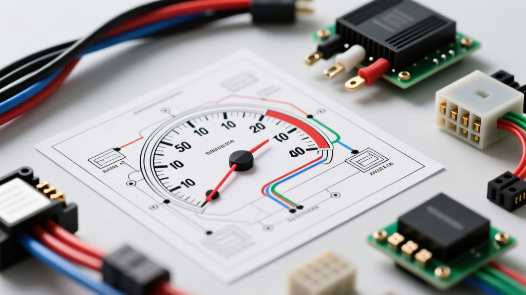
The Hidden Dangers of Misreading a Speedometer Sensor Wiring Diagram
When diagnosing an erratic speedometer, harsh transmission shifts, or a flashing check engine light, technicians and DIYers immediately reach for a speedometer sensor wiring diagram. However, treating these schematics as simple point-to-point maps is a critical error. Modern Vehicle Speed Sensors (VSS) interface directly with the Powertrain Control Module (PCM), Transmission Control Module (TCM), and the instrument cluster via high-speed data buses or sensitive low-voltage square wave signals. Misinterpreting wire color codes, ignoring shielded circuit requirements, or probing with the wrong tools can instantly destroy a $1,200 PCM driver circuit or a $150 sensor. This guide details the most severe wiring mistakes, safety hazards, and proper diagnostic protocols for VSS circuits.
Critical Safety Warnings Before Probing the VSS Circuit
Battery Disconnect and Airbag System Proximity
Before piercing any wire or backprobing a VSS connector, the vehicle's battery must be disconnected, and the supplemental restraint system (SRS) must be given time to deplete its reserve capacitors (typically 3 to 10 minutes). In many older column-shift vehicles and specific front-wheel-drive platforms, the VSS wiring harness routes dangerously close to the steering column clock spring and SRS airbag wiring. SRS circuits are universally identified by yellow loom and yellow connectors. Accidentally shorting a 12V VSS reference wire into a yellow SRS trigger wire can deploy the airbag or blow the SRS diagnostic module.
Avoiding the "Piercing" Trap
Never use a T-pin or sewing needle to pierce the insulation of a VSS signal wire to take a reading. Piercing the insulation exposes the copper strands to moisture and road salt, leading to galvanic corrosion and high-resistance faults months down the road. Furthermore, piercing compromises the integrity of the shielded twisted pair (STP) cabling often used for VSS signals, allowing electromagnetic interference (EMI) to corrupt the square wave signal. Always backprobe the connector from the rear using the correct terminal-specific probes.
Top 4 Speedometer Sensor Wiring Diagram Mistakes
Mistake 1: Confusing Variable Reluctance (VR) with Hall-Effect Sensors
The most catastrophic mistake occurs when a technician assumes all speed sensors operate on the same electrical principle. A wiring diagram will clearly differentiate between a 2-wire Variable Reluctance (VR) sensor and a 3-wire Hall-Effect sensor.
- 2-Wire VR Sensors: These are passive magnetic pickups. They generate their own alternating current (AC) voltage, which increases in frequency and amplitude as vehicle speed increases. They require no external power. If you mistakenly apply 12V or 5V to a VR sensor circuit, you will short the PCM's internal processing circuit.
- 3-Wire Hall-Effect Sensors: These are active sensors requiring a Reference Voltage (usually 5V, 8V, or 12V), a dedicated Ground, and a Signal wire. They output a digital DC square wave. Applying 12V to a 5V Hall-Effect sensor will instantly fry the sensor's internal integrated circuit (IC).
Expert Insight: Chrysler vehicles famously utilize an 8V reference circuit for many Hall-Effect speed and position sensors. If your multimeter reads 8V on the reference wire, do not assume the voltage regulator is failing; it is by design. For more on OEM sensor architectures, refer to the AA1Car Speed Sensor Diagnostics Library.
Mistake 2: Backprobing with Improper Gauge Pins (Terminal Damage)
VSS connectors, typically Delphi Weather-Pack or TE Connectivity AMP series, utilize delicate female terminals designed for 18 AWG to 20 AWG wire. Standard digital multimeter (DMM) probes are far too thick. Forcing a standard probe into the rear of the connector spreads the female terminal's tension fingers. This creates a "pin drag" issue, leading to intermittent signal loss, micro-arcing, and erratic speedometer needle movement. Always use specialized backprobe tools (like the Lisle 39800 kit) or ultra-thin T-pins that match the terminal gauge.
Mistake 3: Ignoring Shielded Wire Requirements for EMI
The signal wire on a Hall-Effect VSS carries a low-amplitude (0-5V) square wave. This signal is highly susceptible to Electromagnetic Interference (EMI) from ignition coils, alternator fields, and high-current fuel pump circuits. According to SAE J1113 Electromagnetic Compatibility Standards, sensitive data and signal circuits must be protected. If you are repairing a broken VSS signal wire, you must use Shielded Twisted Pair (STP) cable and ground the shield drain wire at the PCM end only. Using standard primary automotive wire (GXL/TXL) without shielding will result in the PCM reading "ghost" pulses, causing the speedometer to jump erratically and the transmission to hunt for gears.
Mistake 4: Grounding the Signal Return to the Chassis
A 3-wire VSS circuit includes a "Low Reference" or "Sensor Ground" wire. A common wiring diagram misinterpretation is assuming this ground can be tied to any clean chassis bolt or the engine block. This is false. The Low Reference wire must return directly to the dedicated Sensor Ground pin on the PCM. Grounding it to the chassis creates a "ground loop." Because the engine block and the PCM chassis ground often have a slight voltage potential difference (due to alternator ripple and starter current), this offset is added to the VSS signal wire. A 0.5V ground offset can push a 4.5V high-pulse over the 5V threshold, causing the PCM to drop the signal entirely.
Standard 3-Wire Hall-Effect VSS Pinout & Wire Color Reference
While you must always consult the specific factory service manual for your exact make, model, and year, the following table outlines the typical wire color codes, AWG sizes, and functions for common domestic 3-wire Hall-Effect speedometer sensors.
| Pin / Circuit | Function | Typical GM Wire Color | Typical Ford Wire Color | Typical Chrysler Wire Color | AWG Size |
|---|---|---|---|---|---|
| Pin A | Reference Voltage (Supply) | Pink (5V) | Red / Yellow (12V) | Dark Blue (8V) | 18 AWG |
| Pin B | VSS Signal (Square Wave) | Purple / White | Gray / Black | Dark Green / White | 20 AWG (Shielded) |
| Pin C | Low Reference (Sensor Ground) | Light Green / Black | Black / White | Black / Light Blue | 18 AWG |
Proper Diagnostic Tools: Ditch the Multimeter for an Oscilloscope
While a Digital Multimeter (DMM) can verify the presence of reference voltage and continuity to ground, it is virtually useless for diagnosing a degrading speedometer sensor signal. A DMM's refresh rate is too slow to capture micro-second dropouts in a square wave that is pulsing hundreds of times per second at highway speeds.
Oscilloscope Testing Procedure
According to advanced diagnostic protocols outlined in Haynes Manuals Electrical Testing Procedures, an automotive oscilloscope is mandatory for VSS signal verification.
- Setup: Connect the scope's Channel A to the VSS Signal wire (backprobed). Set the timebase to 10ms/div and the voltage scale to 5V/div (or 12V/div for older Ford systems).
- Ignition On, Engine Off (KOEO): Verify the signal line rests at either 0V or the full reference voltage (pull-up/pull-down configuration depending on OEM).
- Drive on Lift or Road Test: As the wheels turn, the scope should display a perfect, crisp square wave.
- Amplitude: Must swing cleanly from 0V to 5V (or 12V). A "rounded" top indicates high resistance in the circuit or a failing sensor IC.
- Duty Cycle: Most OEM VSS sensors output a 50% duty cycle. If the waveform spends more time high than low (or vice versa), the sensor air gap is incorrect, or the reluctor ring on the differential/axle is damaged.
- Dropouts: Any sudden dips to 0V while the signal is high indicate EMI interference or a broken wire strand making intermittent contact under vibration.
Conclusion
A speedometer sensor wiring diagram is a vital diagnostic tool, but it requires a deep understanding of automotive electrical principles to use safely and effectively. By respecting the differences between VR and Hall-Effect sensors, utilizing proper backprobing techniques to preserve 20 AWG terminals, and strictly adhering to shielded wiring requirements, you can accurately diagnose VSS faults without causing collateral damage to the vehicle's PCM or SRS systems. Always verify your signal with an oscilloscope, and never trust a simple continuity test when dealing with high-frequency digital data circuits.