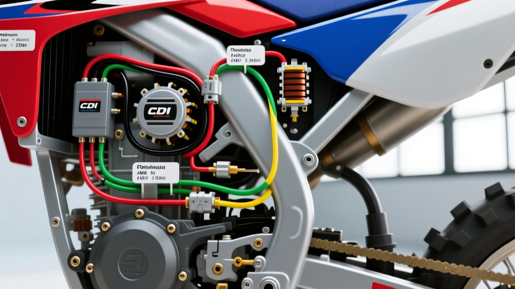
Introduction to 125cc Kick-Start Electrical Architecture
When troubleshooting or rebuilding the electrical system of a carbureted 125cc pit bike (commonly found in SSR, Apollo, Thumpstar, and generic Chinese-manufactured clones), understanding the kick-start wiring diagram is essential. Unlike electric-start models that rely on a 12V battery, starter solenoid, and DC-CDI, kick-start 125cc pit bikes utilize a magneto-driven AC-CDI (Capacitor Discharge Ignition) system. This means the ignition system is entirely self-sustaining; the stator generates the alternating current required to fire the spark plug independently of any battery or external DC power source.
The simplicity of the kick-start harness makes it highly reliable for off-road abuse, but it also means that a single broken ground or corroded bullet connector will result in a complete loss of spark. This technical specification reference details the exact wire color codes, American Wire Gauge (AWG) requirements, stator resistance values, and 6-pin CDI configurations necessary to diagnose, repair, or completely rewire a 125cc kick-start pit bike.
System Architecture and Power Flow
The electrical architecture of a kick-start 125cc pit bike revolves around a dual-coil stator housed within the left-side engine crankcase. The stator features two distinct windings:
- Ignition Source Coil: Generates high-voltage AC (typically 100V to 400V depending on RPM) specifically to charge the CDI unit's internal capacitor.
- Lighting/Trigger Coil Assembly: The lighting coil provides lower-voltage AC for the headlight and taillight, while a separate pickup coil (pulse generator) reads the flywheel magnet to dictate ignition timing.
When the rider engages the kick-starter, the flywheel rotates past the stator. The source coil sends AC voltage via the black/yellow wire to the CDI. Simultaneously, the pickup coil detects the flywheel's timing ridge and sends a low-voltage trigger signal via the blue/white wire. The CDI then discharges its stored energy through the black/red wire to the ignition coil, which steps the voltage up to 20,000+ volts to bridge the spark plug gap.
Standard 6-Pin AC-CDI Connector Pinout
The vast majority of 125cc pit bikes utilize a standardized 6-pin CDI connector (often a 4+2 configuration where one row has 4 pins and the other has 2). Proper pin identification is critical, as aftermarket CDI units may feature different housing layouts despite identical internal circuitry. Below is the industry-standard pinout for a kick-start AC-CDI.
| Pin Number | Wire Color | Circuit Function | Signal Type / Specification |
|---|---|---|---|
| Pin 1 | Blue/White | Pickup Coil Trigger | Low Voltage AC Pulse (0.5V - 3.0V) |
| Pin 2 | Green | System Ground | DC 0V (Chassis/Engine Ground) |
| Pin 3 | Black/White | Kill Switch Circuit | Ground Interrupt (Open = Run, Ground = Stop) |
| Pin 4 | Black/Yellow | Stator Source Power | High Voltage AC (100V - 400V) |
| Pin 5 | Black/Red | Ignition Coil Feed | High Voltage DC Discharge (Capacitor Output) |
| Pin 6 | N/A (Empty) | Not Connected | Reserved for DC-CDI or Tachometer |
Note: Always verify your specific CDI unit's casing diagram. Some manufacturers swap Pin 1 and Pin 4 locations, though the wire colors remain universally consistent across the harness.
OEM Wire Color Codes and AWG Specifications
Adhering to proper wire gauge specifications is vital to prevent voltage drop, insulation melting, or intermittent misfires under high-RPM vibration. According to SAE J1128 standards for low-tension primary automotive cable, the insulation must withstand engine bay temperatures and chemical exposure. Pit bike harnesses typically use PVC or XLPE insulated stranded copper wire.
| Wire Color | Function | Recommended AWG | Connector Type |
|---|---|---|---|
| Black/Yellow | Stator to CDI (Ignition Power) | 18 AWG | 4.8mm Female Spade / Bullet |
| Blue/White | Pickup Coil to CDI (Trigger) | 20 AWG or 18 AWG | 2.8mm Female Spade |
| Green | Main Harness Ground | 16 AWG | 6mm Ring Terminal (Bolted to Frame) |
| Black/White | Kill Switch to CDI | 18 AWG | 4.8mm Female Spade |
| Black/Red | CDI to Ignition Coil | 16 AWG | 4.8mm Male Spade |
| White/Pink | Stator to Headlight (AC) | 16 AWG | 2.8mm Bullet Connectors |
| Yellow | Stator to Taillight/Regulator | 16 AWG | 2.8mm Bullet Connectors |
Stator and Pickup Coil Resistance Diagnostics
When a kick-start 125cc pit bike loses spark, the stator is often wrongly replaced. Before ordering parts, use a digital multimeter (DMM) to test the stator windings. Set your DMM to the Ohms (Ω) setting and disconnect the stator plug from the main harness to test at the source. Reference data compiled by MiniMotoTech and standard Chinese clone service manuals dictates the following resistance parameters:
1. Testing the Ignition Source Coil (Black/Yellow to Green)
Place the positive probe on the Black/Yellow wire terminal and the negative probe on the Green wire terminal (or the stator metal core).
- Specification: 350Ω to 500Ω
- Failure Mode: A reading of 'OL' (Open Line) indicates a broken winding inside the epoxy casing. A reading near 0Ω indicates a short circuit between windings. Both require complete stator replacement.
2. Testing the Pickup/Trigger Coil (Blue/White to Green)
Place the positive probe on the Blue/White terminal and the negative on the Green terminal.
- Specification: 100Ω to 180Ω
- Failure Mode: The pickup coil is highly susceptible to physical damage from flywheel debris. If the resistance is out of spec, the CDI will not receive the timing signal, resulting in a no-spark condition even if the source coil is functioning perfectly.
3. Testing the Lighting Coil (White and Yellow to Green)
- Specification: 0.5Ω to 2.0Ω
- Note: Because the lighting coil uses very thick wire with few wraps, the resistance is extremely low. Use a high-precision multimeter; otherwise, the internal resistance of your test leads may skew the reading.
Kill Switch Circuit and Grounding Troubleshooting
The most common cause of a 'no-spark' issue on a kick-start pit bike is not a failed CDI, but a compromised kill switch circuit. The Black/White wire operates on a normally-open (NO) logic for running, and a closed-circuit (grounded) logic for stopping.
When the rider flips the handlebar kill switch to 'OFF', the switch physically bridges the Black/White wire to the Green ground wire. This immediately grounds out the high-voltage AC coming from the stator before it can charge the CDI's capacitor, killing the engine.
Diagnostic Procedure:
- Disconnect the CDI unit.
- Set the multimeter to Continuity mode.
- Place one probe on the Black/White wire pin in the harness plug and the other on a known good engine ground.
- With the kill switch in the 'RUN' position, the meter should read 'OL' (no continuity).
- With the kill switch in the 'OFF' position, the meter should beep (continuity to ground).
- Common Pitfall: Internal corrosion inside the handlebar switch housing or a pinched Black/White wire rubbing against the steering stem will create a permanent ground, mimicking a killed engine. If your stator tests good but you have no spark, unplug the Black/White wire from the CDI entirely. If spark returns, the fault lies in the handlebar switch or harness routing.
Lighting Coil Integration and AC Regulation
Kick-start 125cc pit bikes do not use a DC battery to power the lights; instead, they run directly off the stator's AC output. The White/Pink wire supplies the headlight, while the Yellow wire supplies the taillight and, if equipped, an AC voltage regulator.
Because the voltage is unregulated AC directly tied to engine RPM, headlight bulbs will dim at idle and brighten at high RPM. To prevent bulbs from blowing out at maximum kick-start RPM (which can generate upwards of 35V AC on the lighting coil), an inline AC voltage regulator is often spliced into the Yellow wire circuit. This regulator shunts excess AC voltage to ground once it exceeds the 12V-14V AC threshold. When upgrading to LED lighting on a kick-start pit bike, you must install an AC-to-DC rectifier converter, as standard LEDs will instantly fail when subjected to raw stator AC current.
Summary of Best Practices
When rebuilding a 125cc kick-start harness, always use dielectric grease on all bullet and spade connectors to prevent moisture ingress, which is highly prevalent in off-road environments. Ensure the main Green ground wire is sanded down to bare metal on the frame or engine block before securing it with a star washer. Proper adherence to these wiring diagrams and resistance specifications will ensure reliable starting and consistent ignition timing across the entire powerband.