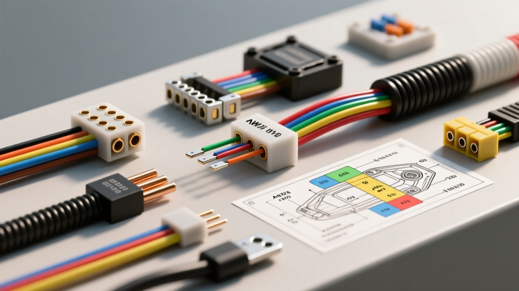
Introduction to Coach & RV Carrier Package Unit Electrical Systems
When troubleshooting roof-mounted HVAC systems in Class A motorhomes, custom transit coaches, or expedition vehicles, accessing the correct carrier package unit wiring diagram pdf is the critical first step. Unlike standard residential split systems, vehicular package units must endure severe vibration, extreme thermal cycling, and dual-voltage environments (120V AC shore/generator power and 12V DC chassis logic). A failure in the wiring harness or control board can lead to catastrophic compressor lockouts or, worse, electrical fires.
From a cost and tool requirements perspective, diagnosing these systems requires a strategic approach. Dealership RV service centers frequently charge $150 to $225 per hour for diagnostic time. By understanding the underlying schematics, wire color codes, and pinout configurations, an owner or independent mobile technician can isolate faults—such as a degraded 12V DC communication wire or a pitted 120V AC contactor—for a fraction of the cost. This guide breaks down the exact tools, material costs, and technical specifications required to service Carrier-based vehicular package units safely and efficiently.
Essential Diagnostic Tools & Estimated Cost Analysis
Working on dual-voltage RV HVAC systems requires tools rated for both low-voltage DC logic and high-voltage AC compressor circuits. Investing in the right diagnostic equipment upfront prevents misdiagnosis and unnecessary part replacement.
| Tool / Material | Specification | Estimated Cost | Primary Application |
|---|---|---|---|
| Fluke 87V Multimeter | True RMS, CAT III 600V | $450 - $500 | Testing 120V AC contactor coils and 12V DC logic boards |
| AC/DC Amp Clamp Meter | 400A range, 100mV/A | $150 - $200 | Measuring compressor LRA (Locked Rotor Amps) without piercing wires |
| SAE J1128 Primary Wire | 10 AWG to 18 AWG (GXL) | $0.40 - $1.20/ft | Replacing UV-degraded or vibration-damaged control harnesses |
| Definite Purpose Contactor | 30A, 120V Coil (e.g., 3100-40122) | $35 - $55 | Replacing pitted or burnt compressor contactors |
| Deutsch DT Connectors | 2-pin to 6-pin kits | $25 - $40 | Weatherproofing exterior thermostat and sensor connections |
Cost Analysis Note: A complete DIY diagnostic kit costs approximately $700. Considering a single dealer diagnostic visit often exceeds $350 before parts are even ordered, the tooling pays for itself after two service events.
Decoding the Carrier Package Unit Wiring Diagram PDF
The core of any Carrier vehicular package unit is the main control board, typically interfaced via a primary terminal block (labeled TB1 or TB2 on the schematic). The wiring diagram bridges the 120V AC high-voltage distribution with the 12V DC microprocessor logic. Below is the standard pinout configuration for a heavy-duty coach application.
Main Terminal Block (TB1) Pinout Specifications
| Terminal | Function | Wire Color | AWG | Voltage Type |
|---|---|---|---|---|
| TB1-1 | L1 Main Power | Black | 10 | 120V AC |
| TB1-2 | Neutral | White | 10 | 120V AC |
| TB1-3 | Chassis Ground | Green | 10 | N/A |
| TB1-4 | 12V DC Logic + | Red | 16 | 12V DC |
| TB1-5 | 12V DC Logic GND | Black | 16 | 12V DC |
| TB1-6 | Compressor Call (Y) | Yellow | 18 | 12V DC |
| TB1-7 | Blower Call (G) | Green | 18 | 12V DC |
| TB1-8 | Heat Strip Call (W) | White | 18 | 12V DC |
When reviewing the carrier package unit wiring diagram pdf, pay special attention to the interlocks between the 12V DC logic calls (TB1-6) and the 120V AC compressor contactor coil. The microprocessor uses a solid-state relay or a low-amperage DC mechanical relay to trigger the high-amperage AC contactor. A common failure point is the corrosion of the 18 AWG yellow wire at the spade connector, which increases resistance and prevents the contactor from fully engaging.
Wire Sizing, AWG Standards, and Voltage Drop Calculations
In large Class A diesel pushers or transit buses, the distance from the basement-mounted 12V DC control panel to the roof-mounted Carrier package unit can easily exceed 35 feet. Using undersized wire for the DC logic circuit is a leading cause of microprocessor resets and erratic HVAC behavior.
SAE J1128 Compliance for Vehicular Applications
All replacement wiring must comply with the SAE J1128 Low Tension Primary Cable Standard. This standard mandates cross-linked polyethylene (GXL or SXL) insulation, which withstands the 125°C temperatures frequently found on RV roofs, unlike standard PVC building wire which will melt and short out.
Voltage Drop Calculation Example
Let us calculate the voltage drop for the 12V DC logic circuit (TB1-4 and TB1-5) running 35 feet (70 feet round trip) drawing 1.5 Amps.
- Using 18 AWG Wire: Resistance is 6.385 ohms / 1000 ft.
Formula: VD = (Length x Current x Resistance) / 1000
VD = (70 x 1.5 x 6.385) / 1000 = 0.67 Volts (5.5% drop). - Using 16 AWG Wire: Resistance is 4.016 ohms / 1000 ft.
VD = (70 x 1.5 x 4.016) / 1000 = 0.42 Volts (3.5% drop).
While a 5.5% drop is generally acceptable for lighting, Carrier microprocessor control boards require stable voltage to maintain EEPROM memory and relay switching. Upgrading the 18 AWG harness to 16 AWG GXL wire costs approximately $12 extra in materials but eliminates ghost faults and board resets.
Real-World Failure Modes & Troubleshooting Decision Tree
Armed with the schematic and a multimeter, follow this decision tree to diagnose the most common vehicular package unit failure: The thermostat calls for cooling, the interior blower engages, but the roof unit clicks rapidly and the compressor fails to start.
Symptom: Contactor Chatter / Compressor Lockout
- Verify 120V AC Input: Measure between TB1-1 (Black) and TB1-2 (White). If voltage is below 110V AC, the issue is in the coach's automatic transfer switch or shore power pedestal, not the HVAC unit.
- Verify 12V DC Logic: Measure between TB1-4 (Red) and TB1-5 (Black) while the thermostat is calling for cooling. If voltage drops below 10.5V DC exactly when the contactor attempts to engage, you have a voltage drop issue in the DC wiring harness or a failing chassis ground.
- Inspect Safety Interlocks: Locate the high-pressure switch on the liquid line. Use your multimeter to check for continuity. If the switch is open, the system is overcharged, or the roof condenser fan motor has failed, triggering a safety lockout.
- Test the Contactor Coil: Disconnect power. Measure the resistance across the 120V AC contactor coil terminals. A healthy coil should read between 10 and 15 ohms. If the meter reads OL (Open Line), the coil is burnt out. Replace the contactor (approx. $40 cost) rather than the entire control board.
Material Costs: Connectors and Environmental Sealing
Vehicular environments expose wiring to constant UV radiation, rain, and road debris. Standard wire nuts or vinyl electrical tape are violations of the NFPA 1192 Standard on Recreational Vehicles for exterior or roof-mounted electrical connections.
When repairing the sensor wiring (such as the outdoor ambient thermistor or freeze-stat), always use adhesive-lined heat shrink tubing and Carrier-approved weatherproof connectors or Deutsch DT series plugs. A kit of adhesive-lined marine-grade heat shrink costs roughly $15 and prevents water ingress that commonly leads to control board short circuits, saving you from a $350+ board replacement.
Summary of Cost Savings
By utilizing the factory schematics, adhering to SAE J1128 wire standards, and performing systematic voltage drop tests, mobile technicians and advanced DIYers can reduce Carrier package unit repair costs by up to 70%. The investment in a True-RMS multimeter and proper automotive-grade crimping tools ensures that repairs withstand the harsh realities of the road, keeping the coach climate-controlled and safe.