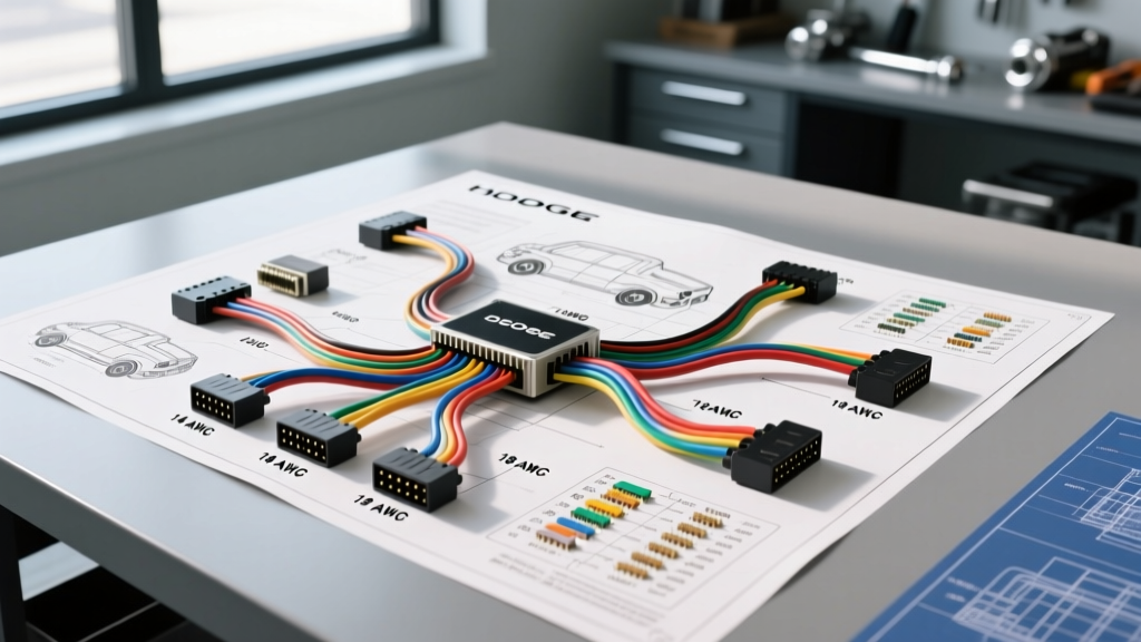
Introduction to Dodge Ram Electrical Architecture
Understanding a factory Dodge truck wiring diagram is essential for diagnosing complex electrical faults, especially in heavy-duty models equipped with the 5.9L and 6.7L Cummins turbodiesel engines or the high-output HEMI V8s. Unlike older, purely analog circuits, modern Dodge Rams utilize a multiplexed network architecture. This includes the Chrysler Collision Detection (CCD) bus, the older PCI (J1850) bus, and the high-speed CAN (J1939/J2534) networks that allow the Engine Control Module (ECM), Transmission Control Module (TCM), and Totally Integrated Power Module (TIPM) to communicate seamlessly. When you pull up a schematic for a 3rd or 4th generation Ram, you are not just looking at power and ground; you are looking at data topologies. This complete walkthrough will dissect the core circuits, ECM pinouts, and critical sensor wiring that every Dodge truck owner and diesel technician must master.
Decoding the Factory Dodge Truck Wiring Diagram
Before probing any connector, you must understand the nomenclature used in Chrysler/Dodge factory service manuals (FSM). Dodge wiring diagrams use a standardized two-letter color code system. For example, a wire labeled 'VT/WT' is Violet with a White tracer stripe, while 'BK/LB' is Black with a Light Blue tracer.
Common Dodge Wire Color Abbreviations:
- BK: Black (Typically chassis or sensor ground)
- RD: Red (Typically fused B+ or battery voltage)
- VT: Violet (Often used for 5V reference signals)
- OR: Orange (Often used for sensor signal returns or CAN High)
- DB: Dark Blue (Often used for CAN Low or multiplexed data)
- DG: Dark Green (Injector control or specific actuator signals)
Furthermore, Dodge diagrams denote splice locations with a unique 'S' number (e.g., S142) and ground locations with a 'G' number (e.g., G105). Ground G100 and G101 are typically located on the left front fender inner panel or directly on the engine block. A poor connection at G101 is a notorious cause of erratic APPS (Accelerator Pedal Position Sensor) readings and random stalling in 5.9L Cummins models. Always verify ground integrity using a voltage drop test before replacing expensive control modules.
Bosch ECM Pinout and Power Distribution Reference
The heart of the Dodge Cummins electrical system is the Bosch EDC (Electronic Diesel Control) module. Depending on the year, it utilizes a 50-pin and a 60-pin connector configuration. Below is a critical reference table for the primary power, ground, and communication pins on the 60-way ECM connector commonly found on 2003-2007 5.9L models.
| Pin Number | Wire Color | Circuit Function | AWG Size |
|---|---|---|---|
| 1, 2, 3 | RD (Red) | Fused B+ (Battery Voltage via TIPM/Relay) | 14 AWG |
| 4, 5 | BK (Black) | Power Ground (Engine Block to Chassis) | 14 AWG |
| 6 | PK/BK (Pink/Black) | Ignition Run/Start Signal | 18 AWG |
| 12 | OR/DG (Orange/Dark Green) | CAN High (+) J1939 Data Link | 20 AWG |
| 13 | OR/LB (Orange/Light Blue) | CAN Low (-) J1939 Data Link | 20 AWG |
| 24 | VT/WT (Violet/White) | 5V Reference Supply (Sensors) | 18 AWG |
| 45 | OR/DB (Orange/Dark Blue) | APP Signal 1 (Potentiometer 1) | 18 AWG |
Reference: For comprehensive multiplexing standards and CAN bus topology, consult the SAE International J1939 standard documentation, which governs heavy-duty vehicle network communications.
Deep Dive: Accelerator Pedal Position Sensor (APPS) Wiring
The APPS is one of the most failure-prone electrical components on the Dodge Ram 5.9L Cummins. Unlike a simple throttle position sensor, the APPS uses a dual-potentiometer design for redundancy and safety compliance. When analyzing the Dodge truck wiring diagram for the APPS, you will find a 6-wire harness routing from the pedal assembly to the ECM.
APPS Circuit Breakdown
- Pin 1 (5V Reference): Violet/White (VT/WT). Supplies a precise 5.0V from the ECM. If this drops below 4.8V, suspect a short in the MAP sensor or wiring harness chafing.
- Pin 2 (Signal 1): Orange/Dark Blue (OR/DB). The primary throttle position signal. Should read ~0.5V at idle and sweep smoothly to ~3.8V at Wide Open Throttle (WOT).
- Pin 3 (Ground): Black/Light Blue (BK/LB). Sensor return path to the ECM. Must have less than 0.05V drop under load.
- Pin 4 (5V Reference): Violet/White (VT/WT). Secondary 5V supply.
- Pin 5 (Signal 2): Orange/Yellow (OR/YL). Secondary signal, typically reading exactly half the voltage of Signal 1 for redundancy verification.
- Pin 6 (Ground): Black/Light Blue (BK/LB). Secondary ground.
Troubleshooting Insight: 'Dead pedal' syndrome is often caused by fretting corrosion inside the APPS connector cavity rather than a failed sensor. Moisture wicks into the connector via capillary action. When diagnosing, never pierce the wire insulation with a multimeter probe; this creates a pathway for copper oxidation. Instead, use proper back-probe pins or a T-harness adapter to read live data. For a permanent fix, apply dielectric grease (like NYE 812A) to the connector terminals and ensure the harness is routed away from the engine fan to prevent vibration-induced micro-disconnects.
High-Current Circuits: Grid Heater and Starter Solenoids
Dodge trucks equipped with the Cummins engine rely on massive current draws for cold-weather starting and cranking. The Intake Air Grid Heater is a prime example of a high-amperage circuit that frequently causes wiring harness meltdowns if not maintained according to factory specifications.
The grid heater relay is typically mounted on the passenger side valve cover or inner fender. When the ECM commands the grid heater ON, the relay closes, pulling upwards of 180 to 210 Amps directly from the passenger-side battery. The factory wiring diagram specifies a 2/0 AWG or minimum 4 AWG battery cable for this circuit. A common aftermarket mistake is replacing a corroded factory cable with a standard 8 AWG or 6 AWG wire. Under a 200A load, an 8 AWG wire will act as a resistor, generating extreme heat, melting the insulation, and causing a catastrophic voltage drop that starves the ECM of operating voltage, resulting in an immediate engine stall.
When rebuilding or repairing the grid heater circuit, always use pure copper (not Copper-Clad Aluminum, CCA) cables, and terminate them with closed-end, adhesive-lined heat shrink ring terminals. Torque the battery and relay terminal nuts to the manufacturer specification (typically 80-100 in-lbs for M8 studs) to prevent micro-arcing.
Harness Repair and Weatherproofing Standards
When your Dodge truck wiring diagram leads you to a broken wire or a corroded splice, the repair methodology is just as critical as the diagnosis. The under-hood environment of a diesel truck is subjected to extreme heat cycles, high-pressure wash water, and severe vibration.
The 'Solder and Shrink' Myth
While many DIYers believe soldering is the ultimate repair, Bosch automotive engineering guidelines and OEM standards heavily favor crimping for high-vibration environments. Solder creates a rigid joint that can suffer from fatigue cracking just outside the solder wick line due to the stiffness differential between the bare wire and the soldered section.
Best Practice Repair Protocol:
- Strip: Use precision wire strippers to avoid nicking the copper strands. For 18 AWG sensor wires, strip exactly 5mm of insulation.
- Crimp: Use an open-barrel or closed-barrel crimp terminal with a ratcheting crimper calibrated for the specific AWG. A proper crimp performs a cold-weld, deforming the terminal and wire into a single solid mass.
- Seal: Slide a piece of dual-wall, adhesive-lined polyolefin heat shrink tubing over the joint. Apply heat evenly until the inner adhesive layer melts and extrudes slightly from the ends. This creates a 100% waterproof, strain-relieved seal that meets IP67 standards.
For connectors that are completely degraded, bypass the factory push-lock terminals and upgrade to Haynes-recommended aftermarket Deutsch DT or Weather-Pack connectors. These utilize solid copper core pins, silicone rear seals, and positive locking wedges that are virtually immune to the vibration and moisture that plague standard OEM blade connectors.
Summary: Methodical Diagnosis is Key
Navigating a Dodge truck wiring diagram requires more than just tracing lines; it requires an understanding of module logic, network topologies, and the physical realities of under-hood environments. By respecting OEM wire gauges, utilizing proper back-probing techniques, and executing aerospace-grade harness repairs, you can eliminate the 'electrical gremlins' that plague heavy-duty pickups and ensure your Ram operates reliably for hundreds of thousands of miles.