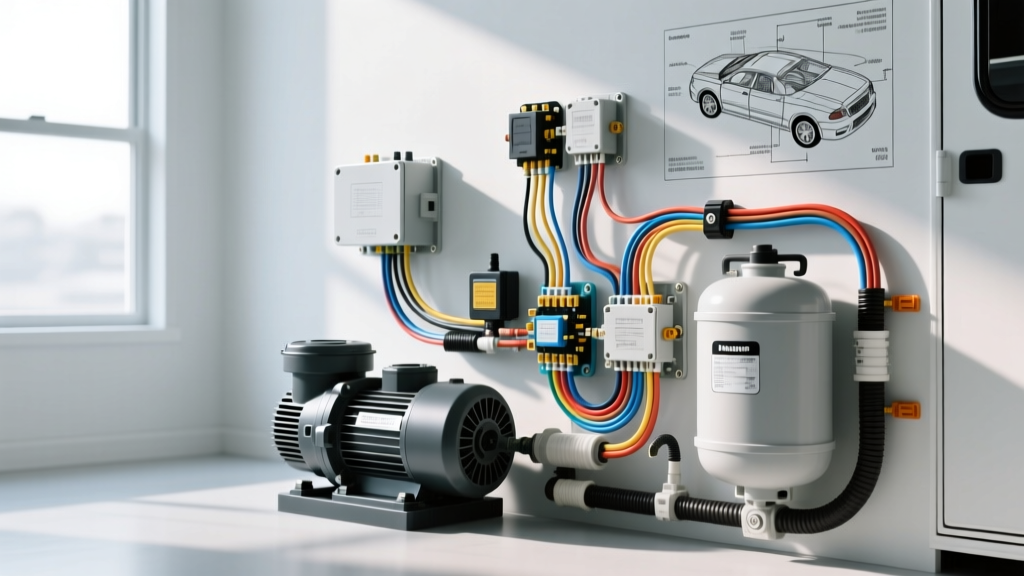
Mobile Septic Systems: Automotive Wiring vs. Residential Plumbing
When mobile service technicians, RV owners, and portable sanitation fleet managers search for a wiring diagram for septic system configurations, they frequently encounter residential schematics designed for 120V or 240V AC lift stations and aerators. However, mobile sanitation vehicles, motorhomes, and vacuum trucks rely entirely on 12V or 24V DC automotive electrical architectures. Applying residential wiring logic to a mobile black water or septic pumping system is a primary cause of electrical fires, voltage drop failures, and catastrophic galvanic corrosion.
This technical guide provides the definitive automotive wiring framework for vehicle-mounted septic systems, focusing on 12V DC macerator pumps, capacitive tank level sensors, and PTO-driven vacuum controls. We will cover critical safety warnings, OEM wire color codes, AWG sizing, and relay pinouts required to maintain a safe, IP67-rated electrical environment in highly corrosive underbelly zones.
Critical Safety Warnings for Mobile Septic Electrical Systems
The underbelly of a motorhome or the chassis of a septic pump truck is one of the most hostile electrical environments on a vehicle. Wiring in these zones is exposed to hydrogen sulfide gas, raw effluent, road salt, and high-pressure washdowns.
- Galvanic Corrosion & Tinned Wire: Never use standard automotive copper wire (SAE J1128) in a septic or black water zone. You must use SAE J378 marine-grade, stranded tinned copper wire. The tin coating prevents the copper from oxidizing and turning black/green when exposed to sulfur-rich septic gases.
- Hydrogen Sulfide Ignition Risk: Black water tanks generate methane and hydrogen sulfide. All electrical connections inside or immediately adjacent to the tank vault must be hermetically sealed using dual-wall, adhesive-lined heat shrink tubing. Exposed crimp connectors can arc and ignite trapped gases.
- Chassis Grounding Prohibitions: Do not use the vehicle chassis as a negative ground return for septic pumps or sensors in wet zones. Road grime and rust create high-resistance grounds. Always run a dedicated 10 AWG or 12 AWG white ground wire directly back to the main DC distribution bus or battery negative terminal.
Standard 12V Macerator Pump Wiring Diagram & Relay Logic
A typical RV or mobile sanitation macerator pump (such as the Flojet or Shurflo 12V models) draws between 12A and 15A under load, with a startup surge that can exceed 25A. Because of this amperage, the control switch on the dashboard or exterior service bay cannot handle the direct current load. A standard 5-pin Bosch-style automotive relay is required.
5-Pin Bosch Relay Pinout Configuration
| Pin Number | Function | Wire Color (OEM Std) | Connection Destination |
|---|---|---|---|
| 30 | Constant 12V+ Power | Red (10 AWG) | Battery Positive (via 20A Inline Fuse) |
| 87 | Normally Open (NO) Output | Red (10 AWG) | Macerator Pump Positive Terminal |
| 85 | Relay Coil Ground | White (14 AWG) | Chassis Ground or DC Bus Negative |
| 86 | Switched 12V+ Trigger | Yellow (14 AWG) | Dashboard / Service Bay Momentary Switch |
| 87a | Normally Closed (NC) | Not Used | Insulated and capped (Heat shrink) |
Circuit Protection & AWG Sizing Chart
Voltage drop is the silent killer of mobile septic pumps. If a 12V macerator pump receives less than 10.5V due to undersized wiring over a long distance, the motor will overheat, draw excessive amperage, and eventually fail. Use the following chart based on the total round-trip wire length (positive + negative) to size your conductors correctly.
| Total Wire Run (Round Trip) | Required AWG Size (15A Load) | Voltage Drop (Approx) | Recommended Fuse Rating |
|---|---|---|---|
| 0 - 15 Feet | 12 AWG | 0.30V (2.5%) | 20A ATC Blade |
| 16 - 25 Feet | 10 AWG | 0.38V (3.1%) | 20A ATC Blade |
| 26 - 40 Feet | 8 AWG | 0.38V (3.1%) | 25A ATC / Maxi |
Tank Level Sensor Wiring: Resistive vs. Capacitive
Modern septic service trucks and motorhomes utilize either resistive probe sensors or non-contact capacitive sensors to monitor black water tank levels. Capacitive sensors are heavily preferred in septic applications because they adhere to the outside of the polyethylene tank, eliminating the risk of internal probe corrosion and effluent leaks.
When wiring a standard 4-pad capacitive sensor module, the harness typically utilizes a 4-pin AMP Superseal 1.5 or Deutsch DT connector to ensure waterproof integrity.
- Pin 1 (Red): 12V+ Ignition or Switched Power (18 AWG)
- Pin 2 (Black): Signal Output to Monitor Panel (18 AWG)
- Pin 3 (White): Dedicated Clean Ground (18 AWG)
- Pin 4 (Green): Shield / Drain Wire (Grounded at panel only to prevent ground loops)
Expert Warning: Never splice into a shared ground wire that services high-draw inductive loads like water pumps or slide-out motors. The inductive kickback and alternator ripple will cause the capacitive septic sensors to read erratically, showing a full tank when it is empty.
Top 5 Fatal Wiring Mistakes in Mobile Septic Systems
- Fusing at the Switch Instead of the Battery: The inline fuse must be placed within 18 inches of the battery positive terminal. If a 10 AWG wire chafes against the steel chassis frame 20 feet down the line and the fuse is located at the dashboard switch, the entire 20-foot wire run will melt and potentially ignite the vehicle floor.
- Using Standard Butt Splices: Standard vinyl or nylon insulated crimp connectors will wick moisture via capillary action. In a septic environment, this leads to rapid copper oxidation. Always use adhesive-lined, marine-grade heat shrink butt splices.
- Ignoring IP67 Switch Ratings: Exterior service bay switches controlling the macerator pump must be rated IP67 or higher. Standard automotive rocker switches will allow water ingress, leading to internal short circuits and parasitic battery drains.
- Routing Signal Wires with High-Voltage Inverter Cables: If your motorhome has a 2000W inverter for residential appliances, routing the low-voltage septic sensor signal wires parallel to the 120V AC inverter cables will induce electromagnetic interference (EMI), resulting in false tank readings.
- Omitting the Flyback Diode: While modern macerator pumps often include internal snubber circuits, adding an external 1N5408 flyback diode across the pump terminals (cathode to positive, anode to negative) protects the dashboard switch and relay contacts from destructive inductive voltage spikes when the pump is turned off.
Troubleshooting Decision Matrix: Macerator & Sensor Failures
| Symptom | Probable Cause | Diagnostic Action & Fix |
|---|---|---|
| Pump hums but impeller does not spin | Voltage drop / Undersized wiring | Measure voltage at pump terminals under load. If below 10.5V, upgrade wire gauge or clean battery terminals. |
| Relay clicks rapidly (chattering) | High resistance ground or failing switch | Bypass dashboard switch with a jumper wire. If relay holds, replace switch. Check Pin 85 ground continuity. |
| Tank reads 'Full' when empty | Capacitive sensor calibration drift / Moisture | Clean exterior tank surface with isopropyl alcohol. Recalibrate sensor module per OEM instructions. Check for condensation. |
| Blown 20A fuse immediately upon engagement | Seized impeller or dead short | Disconnect pump harness. Test switch circuit. If fuse holds, inspect pump housing for solidified waste or foreign debris. |
Conclusion & Industry Standards
Designing and maintaining the electrical infrastructure for a mobile black water or septic pumping system requires strict adherence to automotive and marine electrical standards. By utilizing SAE J378 tinned wire, dedicated ground returns, and properly fused Bosch relay circuits, technicians can ensure that the vehicle's sanitation systems operate reliably without posing a fire or shock hazard. For comprehensive compliance, always cross-reference your custom builds with the NFPA 1192 Standard on Recreational Vehicles and the RVIA low-voltage wiring guidelines.