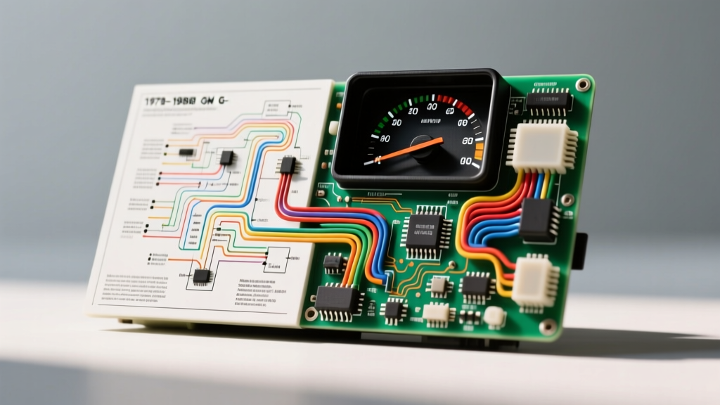
Introduction to the G-Body Instrument Panel Architecture
The General Motors G-Body platform, encompassing iconic models like the Monte Carlo, Grand Prix, Regal, Cutlass, and Malibu from 1978 to 1988, represents a transitional era in automotive electrical design. Understanding the G-Body gauge cluster wiring diagram is essential for any restoration, LS-swap integration, or electrical troubleshooting project. Unlike modern vehicles that rely on multiplexed CAN-bus networks, the G-Body Instrument Panel Cluster (IPC) utilizes a dedicated, hardwired analog topology. Each gauge and indicator light relies on a discrete physical circuit routed from the fuse block, bulkhead connector, or engine control module directly to the cluster's printed circuit board (PCB).
This complete walkthrough dissects the primary harness connector, sender circuit logic, and PCB trace pathways. Whether you are diagnosing a dead fuel gauge or integrating an aftermarket tachometer, tracing these circuits methodically is the only way to ensure reliable operation. According to the factory service documentation published by Helm Incorporated, the G-Body IPC relies on a centralized multi-pin connector that mates directly to the rear of the flexible or rigid PCB, making connector pin condition just as critical as the wire harness itself.
Prerequisites and Safety Protocols
Before probing any circuits or removing the instrument panel bezel, strict safety and anti-static protocols must be followed. The G-Body PCB is highly susceptible to damage from static discharge and physical flexing.
- Power Isolation: Disconnect the negative battery terminal (typically a 10mm or 13mm bolt) to prevent shorting the switched 12V ignition feed against the metal dashboard frame.
- Anti-Static Protection: Wear an ESD wrist strap when handling the exposed PCB. The copper traces are bonded to a fragile Mylar backing (on 1978-1981 models) or a rigid phenolic board (1982-1988 models) and will snap if bent past a 15-degree angle.
- Testing Equipment: Use a high-impedance digital multimeter (DMM) and a variable resistor (potentiometer) rated for 0-2000 ohms to simulate sender units without applying direct voltage to the gauge coils.
Main Harness Connector Pinout Walkthrough
The core of the G-Body gauge cluster wiring diagram centers around the main rectangular harness connector. While early 1978-1980 models utilized a slightly different edge-card configuration, the 1981-1988 models standardized on a 12-pin to 14-pin rectangular plug. Below is the definitive pinout for the standard 1981-1988 analog gauge package.
| Pin | Wire Color | Function | AWG | Circuit Origin |
|---|---|---|---|---|
| A | Pink | Switched 12V Ignition (IGN) | 16 | Fuse Block (IGN) |
| B | Black | Primary Ground | 16 | Kick Panel Ground Bus |
| C | Gray | Instrument Illumination | 18 | Headlight Switch Rheostat |
| D | Tan | Fuel Level Sender Signal | 20 | Tank Sending Unit |
| E | Dark Green | Coolant Temperature Sender | 20 | Intake Manifold Sender |
| F | Brown | Oil Pressure Sender Signal | 20 | Block Sender / ECM |
| G | White | Tachometer Signal (HEI) | 20 | Distributor Tach Terminal |
| H | Dark Blue | High Beam Indicator | 20 | Dimmer Switch / Column |
| J | Light Green | Right Turn Indicator | 20 | Flasher Module / Column |
| K | Dark Green | Left Turn Indicator | 20 | Flasher Module / Column |
| L | Yellow | Brake Warning / Proportioning | 20 | Brake Combo Valve |
| M | Purple | Seatbelt / Key Warning | 20 | Timer Buzzer Module |
Tracing Power, Ground, and Illumination
The Pink (Pin A) wire provides switched 12V power sourced from the ignition switch's 'RUN' and 'BULB TEST' positions. If your gauges are completely dead, verify voltage at Pin A with the key in the 'RUN' position. The Black (Pin B) wire grounds the entire cluster to the left kick panel ground bus. A poor ground here causes 'ghosting,' where illuminating the turn signal causes the fuel gauge to drop because the current seeks an alternative path to ground through the sender circuits.
The Gray (Pin C) illumination circuit is unique. It originates at the headlight switch rheostat. As you rotate the headlight knob, the rheostat alters the resistance on the ground side of the illumination bulbs, dimming the PC194 bulbs embedded in the cluster. If your dash lights flicker when hitting bumps, the issue is rarely the cluster; it is almost always the oxidized rheostat coil inside the headlight switch assembly.
Engine Sender Circuits: Resistance and Diagnostics
The most frequently troubleshooted section of any G-Body gauge cluster wiring diagram involves the analog sender circuits (Pins D, E, and F). GM utilized a variable-resistance thermistor/sender design. The gauge cluster contains an electromagnetic coil that reacts to the voltage drop across the sender. If the sender wire (e.g., Tan for fuel) shorts to ground, the gauge will read full/empty depending on the specific calibration, but usually pegs to the extreme.
To properly diagnose a faulty gauge versus a faulty sender, you must bypass the vehicle wiring and test the cluster directly using a potentiometer. The community-verified trace paths found in the GBodyForum Factory Wiring Diagrams archive confirm the following resistance specifications for GM G-Body analog gauges.
| Gauge | Wire Color | Empty/Cold Resistance | Full/Hot Resistance | Tester Setting |
|---|---|---|---|---|
| Fuel Level | Tan | 0 Ohms (Empty) | 90 Ohms (Full) | 0-100 Ω Potentiometer |
| Coolant Temp | Dark Green | ~1365 Ohms (Cold) | ~65 Ohms (Hot) | 0-2000 Ω Potentiometer |
| Oil Pressure | Brown | 0 Ohms (No Pressure) | 90 Ohms (Max Press) | 0-100 Ω Potentiometer |
Step-by-Step Sender Circuit Testing
- Disconnect the main cluster harness.
- Connect one lead of your variable resistor to the Pink wire cavity (Switched 12V) and the other lead to the Tan wire cavity (Fuel).
- Turn the ignition to 'RUN'.
- Sweep the potentiometer from 0 to 90 ohms. The fuel needle should smoothly traverse from 'E' to 'F'.
- If the needle moves correctly during the bench test but fails in the vehicle, the fault lies in the Tan wire harness (chafing near the bulkhead) or the in-tank sending unit float arm.
Printed Circuit Board (PCB) and Bulb Tracing
Once the harness leaves the main connector, the signals are distributed across the PCB. Early G-Bodies used a flexible Mylar printed circuit, while later years transitioned to rigid phenolic boards. Both suffer from a common failure mode: the copper foil traces delaminate or corrode at the bulb socket contact points.
The illumination bulbs are typically PC194 wedge-base lamps. Because these incandescent bulbs generate significant heat, the plastic socket tabs and the underlying copper pads on the PCB frequently melt or oxidize. This creates a high-resistance joint, resulting in dim or dead gauge faces. When repairing these traces, do not use standard rosin-core solder, as the heat can melt the Mylar backing. Instead, use conductive silver epoxy and copper foil tape to bridge broken traces, a method that aligns with low-voltage repair standards outlined in SAE J1128 specifications for automotive wire and trace maintenance.
Upgrading to LED Illumination
Many restorers upgrade the PC194 incandescent bulbs to 194-LED equivalents to reduce heat and draw less current. However, the G-Body headlight switch rheostat requires a minimum electrical load to function correctly and prevent voltage spikes. If you replace all dash bulbs with low-draw LEDs, the rheostat may overheat or fail to dim the circuit properly. To resolve this, install a 10-ohm, 10-watt dummy load resistor in parallel with the Gray illumination wire behind the cluster to simulate the factory incandescent amperage draw.
Tachometer Signal and HEI Integration
For G-Bodies equipped with a factory tachometer, the White wire (Pin G) carries the pulsed signal from the HEI (High Energy Ignition) distributor. This wire connects directly to the 'TACH' terminal on the HEI cap. A common failure mode is the use of standard 20 AWG wire for long routing, which acts as an antenna and picks up alternator whine or RFI (Radio Frequency Interference). If your tachometer needle bounces erratically at idle, verify that the White wire is routed away from the spark plug wires and consider adding a 0.01µF ceramic capacitor between the TACH terminal and ground to filter out high-frequency noise.
Summary and Final Verification
Mastering the G-Body gauge cluster wiring diagram requires moving beyond simple continuity testing. By understanding the specific resistance values of the GM senders, the unique grounding topology of the illumination rheostat, and the physical vulnerabilities of the PCB traces, you can accurately isolate faults. Always verify harness pin tension before seating the connector; a loose Pin B (Ground) will cause cascading, illogical failures across multiple gauges, leading inexperienced technicians to mistakenly replace a perfectly functional instrument cluster.