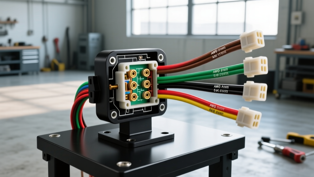
Introduction to Wiper Switch Topologies and Circuit Architecture
Understanding a wiper switch wiring diagram requires moving beyond basic continuity testing and recognizing the distinct architectural shifts in automotive electrical systems. Historically, wiper stalks acted as heavy-duty mechanical routing switches, directly carrying the full amperage load of the wiper motor. In modern vehicles, the stalk has been reduced to a low-current signal generator, utilizing either analog voltage dividers or digital LIN (Local Interconnect Network) bus transceivers to communicate driver intent to a Body Control Module (BCM).
This technical specification reference bridges the gap between classic direct-wire topologies and modern multiplexed networks. We will dissect the industry-standard General Motors 5-pin column-mount wiper switch—found in millions of C/K trucks, G-bodies, and F-bodies—before transitioning to the diagnostic parameters of contemporary BCM-integrated systems. Whether you are restoring a classic vehicle or diagnosing a parasitic draw on a late-model platform, mastering these pinouts, wire gauges, and failure modes is critical for accurate electrical repair.
Classic 5-Pin Wiper Switch Wiring Diagram (GM C/K & G-Body Reference)
The classic GM 5-pin wiper switch is a masterclass in analog circuit design. Unlike modern systems, this switch directly handles the motor's operational current. The wiper motor itself typically features a 3-pin or 4-pin connector, but the column-mounted switch requires a 5-pin harness to manage low speed, high speed, intermittent delay, washer pump actuation, and switch illumination grounding.
Below is the definitive pinout reference for the standard 5-pin column switch harness. Note that wire colors can vary slightly by exact model year, but the AWG sizing and terminal functions remain consistent across the platform.
| Terminal / Pin | Function | OEM Wire Color | AWG Size | Connector System |
|---|---|---|---|---|
| Pin A | Low Speed Motor Feed | Dark Green | 16 AWG | Metri-Pack 280 |
| Pin B | High Speed Motor Feed | Light Blue | 16 AWG | Metri-Pack 280 |
| Pin C | Washer Pump Ground Switch | Yellow | 18 AWG | Metri-Pack 150 |
| Pin D | Switch Illumination / Ground | Black | 18 AWG | Metri-Pack 150 |
| Pin E | Intermittent / Pulse Signal | Gray | 18 AWG | Metri-Pack 150 |
Current Draw and Wire Gauge Specifications
According to the SAE J1128 Low Tension Primary Cable Standard, 16 AWG GXL (Cross-linked) wire is rated for approximately 10 to 15 amps depending on ambient under-dash temperatures. A standard OEM wiper motor draws between 5 to 8 amps on low speed and 8 to 12 amps on high speed. However, the inrush current when the motor starts from a dead stop can briefly spike to 18 amps. The 16 AWG Dark Green and Light Blue circuits are engineered to handle this transient spike without excessive voltage drop, provided the Metri-Pack 280 terminals are free of micro-corrosion.
The Washer Pump Ground-Switching Anomaly
A critical diagnostic trap for novice technicians is the washer pump circuit (Pin C, Yellow). In this topology, the washer pump receives a constant 12V feed directly from the fuse block. The wiper switch does not switch the positive voltage; instead, it switches the ground path. When the driver pulls the stalk backward, Pin C completes the ground circuit through the Black wire (Pin D) to the chassis. If your washer pump has 12V at the connector but fails to run, the fault lies in the wiper switch's internal ground contacts or the Yellow wire's continuity to the stalk, not the pump itself.
Internal Resistor Network and Pulse Board Integration
The intermittent wiper function on analog systems is not controlled by a solid-state timer inside the switch itself. Instead, the wiper stalk contains a variable resistor (potentiometer) connected to Pin E (Gray). As the driver rotates the delay collar on the stalk, the wiper arm moves across a carbon resistive track, altering the resistance sent to the 'pulse board' or delay module located near the wiper motor.
- Minimum Delay (Fastest Wipe): ~500 Ohms
- Maximum Delay (Slowest Wipe): ~15,000 Ohms (15kΩ)
The pulse board reads this resistance via a voltage divider circuit. If the intermittent wiper is stuck on a single delay setting regardless of collar position, the carbon track inside the switch stalk is likely worn or contaminated with dielectric grease. Cleaning the track with electronic contact cleaner or replacing the stalk assembly is required. Furthermore, if the wipers fail to 'park' and stop mid-windshield, the fault is rarely the column switch; it is almost always the internal copper cam switch located inside the wiper motor gear housing that has lost continuity.
Modern Multiplexed Wiper Switch Systems (LIN Bus & Analog Dividers)
In vehicles manufactured from the mid-2000s onward, routing high-amperage motor feeds through the steering column became a packaging and safety liability. Modern wiper switch wiring diagrams reflect a shift toward multiplexing. The stalk now outputs a low-current signal to the BCM, which in turn triggers high-amperage relays or solid-state MOSFETs to power the wiper motor.
Analog Voltage Divider Topology
Many Ford and Chrysler platforms utilize an analog voltage divider. The BCM sends a 5V or 12V reference signal to the switch. Internal resistors within the switch drop the voltage based on the stalk position. The BCM's ADC (Analog-to-Digital Converter) reads the return voltage:
- Off: 5.0V (Open Circuit)
- Low Speed: ~3.8V
- High Speed: ~2.1V
- Intermittent 1: ~1.2V
- Intermittent 2: ~0.6V
Diagnostic Tip: If the BCM detects a voltage outside these predefined thresholds (e.g., 2.8V due to a corroded connector adding series resistance), it will default to a fail-safe mode, usually locking the wipers into high-speed continuous operation to ensure driver visibility.
LIN Bus (Local Interconnect Network) Topology
Late-model platforms (e.g., 2015+ GM and European marques) use a dedicated microcontroller inside the wiper stalk. The wiper switch wiring diagram for a LIN-based stalk is remarkably simple, featuring only three wires:
- Battery Positive (B+): 12V constant, 20 AWG, fused at 5A.
- Ground: Chassis ground, 20 AWG.
- LIN Data Line: Serial communication to the BCM, 22 AWG shielded.
The LIN bus operates at a standard baud rate of 19.2 kbps. As detailed in NXP's LIN Bus Application Notes, the master node (BCM) sends a header frame, and the slave node (wiper stalk) responds with a data frame containing the switch state. Diagnosing a LIN bus wiper switch requires an oscilloscope to verify the square-wave voltage transitions between 12V (recessive) and 1V (dominant). A standard multimeter will only show an average DC voltage of roughly 7V to 8V, which is useless for verifying data integrity.
Connector and Terminal Specifications
When repairing or repinning a wiper switch harness, using the correct terminal retention system is vital to prevent intermittent open circuits caused by steering column vibration. The industry standard for these connections is the Aptiv (formerly Delphi) Metri-Pack series.
- Metri-Pack 150: Used for 18-22 AWG signal, ground, and LIN bus wires. Rated for up to 14 amps. Features a secondary lock (TPA - Terminal Position Assurance) to prevent terminal back-out.
- Metri-Pack 280: Used for 14-16 AWG motor feed wires. Rated for up to 30 amps. The wider 2.8mm blade provides the necessary surface area to dissipate heat generated by the wiper motor's inrush current.
Never attempt to crimp a 16 AWG wire into a 280 terminal using a standard 150 die set. Improper crimp profiles will lead to high-resistance connections, resulting in voltage drops that mimic a failing wiper motor.
Diagnostic Decision Tree: Voltage Drop and Continuity Testing
Use the following structured reference to isolate faults in both classic and modern wiper switch circuits. Always perform voltage drop tests under load (with the motor attempting to run) rather than simple continuity tests with the circuit de-energized.
| Symptom | Probable Electrical Cause | Diagnostic Action & Specification |
|---|---|---|
| Wipers operate on High, but not Low. | Open circuit in Low Speed feed or burnt low-speed brush in motor. | Check voltage at motor Pin 1 (Dark Green) with switch on Low. Must be within 0.5V of battery voltage. If 0V, trace back to switch Pin A. |
| Wipers stop randomly mid-windshield. | Failed internal park switch inside the wiper motor gear cap. | The column switch does not control parking. Inspect the motor's internal copper cam and park switch contacts for arcing or carbon buildup. |
| Intermittent delay is stuck on one speed. | Worn potentiometer track inside the steering column stalk. | Measure resistance between Pin E (Gray) and Pin D (Black) while rotating the collar. Resistance should sweep smoothly from 500Ω to 15kΩ. |
| Washer pump runs continuously when ignition is ON. | Short to ground on the Yellow washer pump control wire. | Disconnect the wiper switch connector. If the pump stops, the switch internal contacts are welded closed. If it continues, the Yellow wire is chafed against the steering column bracket. |
| LIN Bus stalk is completely unresponsive. | Loss of B+ reference or open LIN data line to BCM. | Verify 12V at the stalk B+ pin. Connect oscilloscope to LIN pin; verify 19.2 kbps square wave. If flat at 12V, BCM master node is asleep or data line is severed. |
Summary
Whether you are tracing a Dark Green 16 AWG wire through a classic GM steering column or probing a 19.2 kbps LIN bus signal on a late-model multiplexed network, the foundational principles of the wiper switch wiring diagram remain rooted in precise voltage management and load routing. By adhering to SAE wire gauge standards, utilizing proper Metri-Pack terminal crimps, and understanding the distinction between direct-load switching and BCM signal generation, technicians can accurately diagnose and repair wiper system faults on the first attempt, eliminating unnecessary parts swapping and ensuring critical visibility systems operate flawlessly.