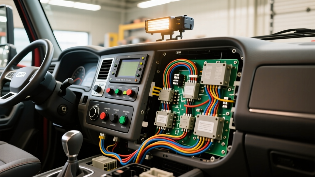
Introduction to Heavy-Duty Multiplexing in Fire Apparatus
Modern fire apparatus engineering has largely abandoned traditional point-to-point relay wiring in favor of sophisticated multiplex electrical architectures. When consulting a Pierce fire truck wiring diagram for models such as the Enforcer, Impel, Arrow XT, or Velocity, you are not simply looking at copper traces and mechanical relays; you are analyzing a localized network of Controller Area Network (CAN) nodes, solid-state switching modules, and pulse-width modulation (PWM) controllers. For fleet mechanics and upfitters, understanding this architecture is critical before initiating any upgrade or modification project.
Attempting to splice into a modern Pierce harness using legacy relay-and-fuse methods will inevitably trigger fault codes, cause voltage irregularities, or violate the stringent electrical safety standards mandated for emergency vehicles. This guide details how to properly interpret Pierce schematics and execute a high-draw auxiliary lighting upgrade—specifically integrating a bank of Whelen Pioneer LED scene lights—directly through the factory Command Zone multiplex system without compromising the chassis CAN bus integrity.
Navigating the Pierce Fire Truck Wiring Diagram
Pierce Manufacturing (an Oshkosh Corporation company) structures its electrical schematics into distinct logical zones. To successfully plan an upgrade, you must locate the correct section of the diagram. A complete Pierce electrical manual is typically divided into:
- Chassis Wiring: Engine ECM, transmission TCM, ABS, and primary SAE J1939 backbone routing.
- Body Multiplex I/O Pages: Input/Output node assignments, pinouts for the Command Zone modules, and solid-state switch ratings.
- Component Location Maps: Physical routing of harnesses through the torque box, cab roof, and body compartments.
For an auxiliary lighting upgrade, your primary focus will be the Body Multiplex I/O Pages. These pages detail the specific pin numbers on the Deutsch and AMP connectors that interface with the multiplex nodes. Unlike a standard automotive wiring diagram where a wire runs directly from a switch to a light, the Pierce diagram will show an input switch (e.g., a momentary rocker on the officer's side panel) sending a low-current signal to a Multiplex Input Node. That node broadcasts a J1939 CAN message to the Output Node, which then grounds or supplies power to the auxiliary circuit via a solid-state FET (Field Effect Transistor) driver.
Understanding the SAE J1939 CAN Bus Backbone
The nervous system of any modern Pierce apparatus is the SAE J1939 CAN bus. Before tapping into any circuit, you must know how to identify and protect the data lines. Splicing into a CAN bus line to draw power will introduce impedance mismatches, causing catastrophic network failures that can disable the engine ECM or multiplex nodes. According to SAE International standards, the J1939 physical layer relies on a twisted pair with specific termination resistances.
| Signal / Function | Standard Wire Color | 9-Pin Deutsch Diagnostic Pin | Voltage / State |
|---|---|---|---|
| CAN High (Data +) | Yellow | Pin C | Dominant: ~3.5V / Recessive: ~2.5V |
| CAN Low (Data -) | Green | Pin D | Dominant: ~1.5V / Recessive: ~2.5V |
| Shield / Drain | Bare / Braided | Pin B | Ground Reference |
| Unswitched Battery (+) | Red | Pin A | 12.5V - 14.2V DC |
| Chassis Ground (-) | Black | Pin E | 0.0V |
Project Scope: Upgrading to High-Draw LED Scene Lights
For this modification project, we are upgrading the rear officer-side scene lighting from standard 1157 incandescent fixtures to four Whelen Pioneer 90W LED flood arrays. While LEDs are highly efficient, a bank of four 90W units operating at 13.8V draws approximately 26 amps continuously. This exceeds the standard 15A or 20A output rating of a single factory multiplex circuit.
Calculating AWG and NFPA 1901 Compliance
Emergency vehicle electrical systems are governed by NFPA 1901: Standard for Automotive Fire Apparatus. NFPA 1901 strictly mandates that the voltage drop on continuous load circuits shall not exceed 3% of the nominal system voltage to ensure life-safety lighting operates at full lumen output. At 13.8V, a 3% drop equates to a maximum allowable loss of 0.414V.
If the run from the rear multiplex output node to the light array is 25 feet (50 feet total round-trip for power and ground), pushing 26 amps through 12 AWG wire would result in a voltage drop of approximately 0.82V (nearly 6%). To comply with NFPA 1901 and prevent thermal degradation of the harness, you must upgrade the output circuit to 8 AWG TXL (Cross-Linked Polyethylene) wire, which reduces the voltage drop to a safe 0.20V over the same distance.
Step-by-Step Integration and Connector Pinning
Because the existing multiplex output circuit is likely rated for only 15A, you cannot simply connect the 26A load directly to the factory node output without risking a node shutdown or melted trace. Instead, the upgrade requires utilizing the multiplex node to trigger an external heavy-duty relay or a Pierce-approved high-current PWM expansion module.
1. Tapping the Multiplex Trigger Signal
Locate the rear body multiplex output node (typically housed in the rear officer-side compartment or torque box). Consult the I/O page of your Pierce fire truck wiring diagram to identify an unused, programmable output circuit, or repurpose the existing 'Scene Light' output pin. Use a Deutsch DT 2-pin extraction tool to carefully back out the factory terminal. Splice an 8 AWG TXL pigtail using a sealed, adhesive-lined heat shrink butt connector, ensuring the splice is located at least 6 inches away from the node connector to prevent moisture wicking via capillary action.
2. External Relay Integration
Mount a heavy-duty, IP67-rated continuous-duty solenoid or a solid-state contactor near the battery distribution block. Wire the 8 AWG trigger line from the multiplex node to the contactor's coil ground. Supply the contactor's load side directly from the main rear power distribution stud using 4 AWG cable, and route 8 AWG TXL to the Whelen Pioneer arrays.
3. Deutsch Connector Pinning and Sealing
Never use standard crimp terminals on fire apparatus exterior wiring. All external connections must utilize Pierce Manufacturing's specified environmental connectors, primarily the Deutsch DT or DTM series. When pinning the DT connectors for the scene lights:
- Strip exactly 5/16" of insulation from the 8 AWG wire.
- Use a calibrated HDT-48-00 crimp tool to ensure a minimum 15 lb pull-test rating.
- Insert the wedgelock (green for 4-pin, gray for 2-pin) until it clicks to secure the terminals.
- Apply a secondary seal using dielectric grease and a molded boot to prevent corrosion from road salts and fireground chemical runoff.
Programming the Command Zone Node
Physical wiring is only half the modification. Because the multiplex system actively monitors circuit current to detect shorts or open circuits, changing the load profile requires software configuration. Connect a laptop to the cab's diagnostic port using a USB-to-CAN adapter and launch the Pierce Command Zone configuration software.
- Navigate to the Output Configuration tab for the rear node.
- Select the circuit assigned to the new scene light trigger.
- Adjust the Expected Current Threshold to match the coil draw of your external contactor (typically 0.5A to 1.2A), rather than the 26A draw of the lights themselves.
- Disable PWM (Pulse Width Modulation) on this specific output, as contactor coils require a steady 12V DC signal and will chatter or fail to engage if subjected to PWM dimming.
- Flash the updated configuration to the node and cycle the ignition to force a network handshake.
Troubleshooting Common Modification Faults
Even with meticulous adherence to the wiring diagram, multiplex modifications can present unique diagnostic challenges. Use this decision tree to resolve common post-upgrade faults:
- Symptom: Multiplex node flashes red/green, scene lights fail to illuminate.
Cause: Under-current fault. The node expects a higher draw but only sees the low-amp contactor coil.
Fix: Recalibrate the lower current threshold in the Command Zone software to match the coil's actual amperage. - Symptom: Lights illuminate for 2 seconds, then shut off; node logs a 'Short to Ground' fault.
Cause: Inrush current spike from the LED drivers exceeds the node's instantaneous overcurrent protection limit.
Fix: Enable the 'Soft Start' or 'Inrush Delay' parameter in the node configuration, or ensure the external contactor is handling the primary load switching rather than the node FET. - Symptom: Intermittent CAN bus communication errors on the dash display when scene lights are active.
Cause: Electromagnetic Interference (EMI) from unshielded high-current LED driver wiring routed parallel to the J1939 CAN bus.
Fix: Reroute the 8 AWG power cables to maintain a minimum 6-inch separation from the yellow/green CAN bus twisted pair, or install a ferrite choke on the LED power feed.
Conclusion
Upgrading auxiliary lighting on a modern fire apparatus requires a fundamental shift from traditional automotive wiring logic to network-aware systems engineering. By carefully interpreting the Pierce fire truck wiring diagram, respecting SAE J1939 data integrity, calculating AWG requirements to NFPA 1901 standards, and properly configuring the multiplex software, fleet technicians can execute high-draw modifications that are both legally compliant and operationally bulletproof on the fireground.