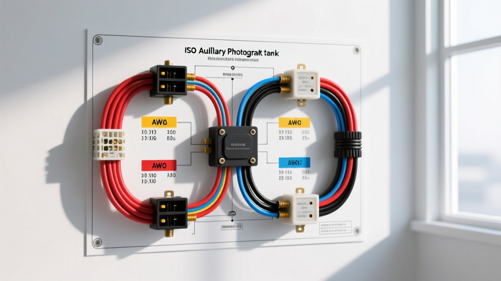
Introduction to Auxiliary Fuel Tank Float Switches
When outfitting a heavy-duty truck, overland expedition vehicle, or commercial fleet rig with an auxiliary fuel tank (such as those from Transfer Flow or Titan Fuel Tanks), managing fuel transfer safely is paramount. The core safety mechanism in these systems is the low-level float switch. This binary sensor prevents the auxiliary transfer pump from running dry, which can lead to catastrophic pump failure, melted wiring, or even a chassis fire. Understanding the wiring diagram of float switch circuits is essential for any automotive electrical technician or advanced DIY installer. This guide provides a comprehensive, practical how-to installation manual for wiring an auxiliary fuel tank float switch, complete with ISO relay pinouts, AWG wire sizing, and real-world troubleshooting protocols.
Understanding the Wiring Diagram of Float Switch Circuits
In a typical aftermarket auxiliary fuel system, the float switch acts as a logical gatekeeper for the fuel transfer pump relay. The transfer pump draws significant current (often 10 to 15 amps under load) and cannot be wired directly through the dash-mounted toggle switch or the float switch itself. Instead, we use a standard Bosch-style 5-pin ISO mini relay to handle the high-current load, while the float switch controls the low-current ground path of the relay coil.
Circuit Logic and Operation
- Normal Operation (Tank Has Fuel): The float is buoyant, keeping the internal reed switch closed. When the driver activates the dash transfer switch, 12V+ flows through the switch to the relay coil (Pin 86). The closed float switch provides a path to ground (Pin 85). The relay energizes, closing the high-current circuit between Pin 30 and Pin 87, powering the transfer pump.
- Low Fuel Condition (Tank Empty): As the fuel level drops, the float descends, opening the internal reed switch. The ground path to Pin 85 is broken. The relay de-energizes, cutting power to the transfer pump instantly, regardless of the dash switch position. This protects the pump from dry-running.
Required Materials & Wiring Specifications
Automotive environments are hostile to electrical connections. Vibration, thermal cycling, and exposure to hydrocarbons demand mil-spec materials. Never use standard vinyl electrical tape or non-sealed crimp connectors under a vehicle chassis.
| Component | Specification / Rating | Application Notes |
|---|---|---|
| Primary Power Wire | 12 AWG TXL (Cross-linked) | Battery to Relay Pin 30, and Relay Pin 87 to Pump. |
| Control Circuit Wire | 16 AWG TXL | Dash switch to Relay Pin 86; Relay Pin 85 to Float Switch. |
| Relay | 5-Pin ISO Mini (Bosch Style) | 40A rating, sealed epoxy potting preferred. |
| Connectors | Deutsch DT Series (2-Pin) | For float switch interface. IP68 waterproof rating. |
| Splices & Terminals | Adhesive-Lined Heat Shrink | Dual-wall polyolefin with meltable inner liner. |
| Fuses | 20A MAXI or ATO Blade | Placed within 18 inches of the battery positive terminal. |
Step-by-Step Installation & Wiring Guide
Follow these steps to execute the wiring diagram of float switch systems safely and reliably, adhering to SAE J1113 Electromagnetic Compatibility and general automotive wiring standards.
- Disconnect the Battery: Isolate the negative terminal on both the primary and secondary (if equipped) batteries to prevent short circuits while routing wires.
- Mount the ISO Relay: Locate a dry, well-ventilated area in the engine bay or under the hood, away from exhaust manifolds. Mount the relay using a stainless steel bracket and zinc-plated hardware. Ensure the relay pins face downward to prevent water ingress into the connector cavity.
- Run the High-Current Power Feed: Route 12 AWG TXL wire from the battery positive terminal to the relay. Install a 20A inline fuse holder within 6 to 18 inches of the battery post. Terminate at Relay Pin 30 using a ring terminal and adhesive-lined heat shrink.
- Wire the Transfer Pump Feed: Run 12 AWG TXL from Relay Pin 87 to the auxiliary transfer pump. Route this wire along the frame rail, securing it every 12 inches with UV-resistant zip ties or P-clips. Maintain a minimum 6-inch clearance from exhaust components.
- Install the Deutsch Connector at the Tank: The float switch typically exits the tank via a sealed sending unit plate. Cut the wire to length and crimp on the Deutsch DT socket contacts using a precision crimp tool. Insert the contacts into the DT housing until they click. Apply a dab of dielectric grease to the mating pins to prevent galvanic corrosion.
- Wire the Control Circuit (Ground Path): Run 16 AWG wire from Relay Pin 85 to the Deutsch connector at the tank. This wire will mate with the float switch's ground output. The other side of the float switch is internally grounded to the sending unit chassis, which must be bonded to the vehicle frame with a dedicated 12 AWG ground strap.
- Wire the Dash Switch Feed: Route 16 AWG wire from an ignition-switched 12V+ source (e.g., upfitter switch output or ACC fuse tap) to the dash-mounted toggle switch. Run the output of the toggle switch to Relay Pin 86.
- Final Grounding: Terminate Relay Pin 87a (if using a 5-pin relay, this is the Normally Closed contact; leave it capped and unused for this specific pump circuit) and ensure the main relay bracket has a clean, bare-metal connection to the chassis for secondary grounding if required by the specific relay model.
Technical Reference: Sender Resistance vs. Binary Switch
It is crucial to distinguish between a binary float switch and a rheostat float sender. Many modern auxiliary tanks combine both into a single unit. According to Delphi Automotive Fuel Systems Tech Resources, the sender provides variable resistance to the dash gauge, while the switch provides the binary cutoff.
| Fuel Level | Binary Float Switch State | Rheostat Sender Resistance (GM 240-33 Standard) | Rheostat Sender Resistance (Ford 0-190 Standard) |
|---|---|---|---|
| Full | Closed (Continuity) | ~240 Ohms | ~160 Ohms |
| Half | Closed (Continuity) | ~100 Ohms | ~20 Ohms |
| Low / Empty | Open (No Continuity) | ~33 Ohms | ~10 Ohms |
Real-World Troubleshooting & Failure Modes
Even with a perfect wiring diagram of float switch schematics, environmental factors can cause system failures. Use this decision tree to diagnose common auxiliary fuel system issues.
Symptom: Transfer Pump Runs Dry (Fails to Shut Off)
- Cause 1: Varnish Binding. In vehicles that sit for long periods or use high-ethanol blends (E15/E85), fuel varnish can build up on the float pivot arm, causing it to stick in the 'up' position even when the tank is empty.
- Fix: Drop the sending unit, clean the pivot arm with aerosol carburetor cleaner, and lubricate with a fuel-safe PTFE spray.
- Cause 2: Reed Switch Welding. If the float switch was wired directly to the pump without a relay (a severe installation error), the inductive kickback from the pump motor can weld the tiny internal reed switch contacts together.
- Fix: Replace the float switch and rewire the system using the ISO relay method detailed above.
Symptom: Transfer Pump Will Not Engage (Tank is Full)
- Cause 1: Chassis Ground Loop. The sending unit relies on a clean chassis ground. If the auxiliary tank is mounted on rubber isolation bushings (common in Transfer Flow Auxiliary Tank Installation Guides to prevent galvanic corrosion), the float switch may lack a return path to the battery.
- Fix: Install a dedicated 12 AWG copper ground strap from the sending unit mounting flange directly to a clean, sanded point on the vehicle frame.
- Cause 2: Voltage Drop on Control Circuit. Corrosion in the Deutsch connector or a poor crimp on Pin 85 can cause a voltage drop, preventing the relay coil from reaching the minimum 9V pull-in threshold.
- Fix: Perform a voltage drop test across the float switch with the ignition on. A reading greater than 0.2V indicates high resistance; re-crimp or replace the Deutsch pins.
Conclusion
Mastering the wiring diagram of float switch configurations ensures your auxiliary fuel system operates safely and reliably across thousands of miles of harsh terrain. By utilizing sealed Deutsch connectors, adhesive-lined heat shrink, and proper ISO relay logic, you eliminate the most common points of failure in aftermarket fuel systems. Always verify your specific sender's resistance curve and switch state with a digital multimeter before finalizing the harness routing.