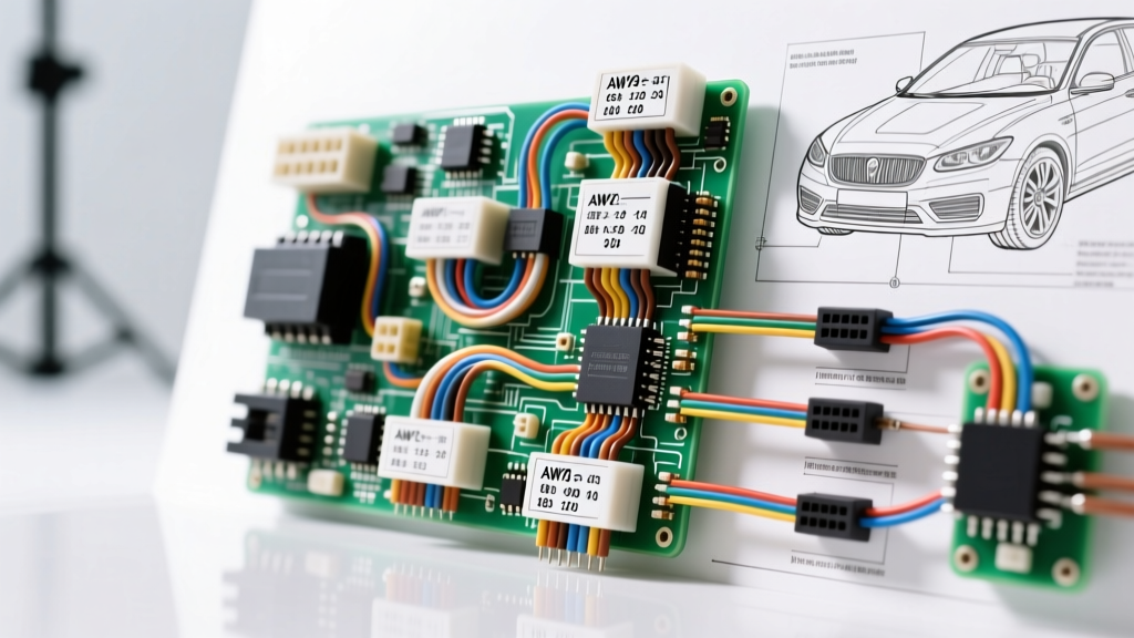
Why Static PDFs Fail Complex Modification Projects
When executing high-level upgrade and modification projects—such as a standalone ECU conversion, a custom LS engine swap, or a comprehensive aftermarket lighting and relay overhaul—relying on static factory service manual PDFs is a recipe for disaster. Factory wiring diagrams are designed for point-to-point diagnostics, not for the synthesis of entirely new harnesses. They lack dynamic netlist validation, do not calculate voltage drop over extended wire runs, and cannot generate automated cut lists. For modern fabricators and motorsport engineers, utilizing dedicated vehicle wiring diagram software is no longer a luxury; it is a critical requirement for ensuring electrical reliability, safety, and performance.
Core Features of Professional Vehicle Wiring Diagram Software
Transitioning from generic drawing tools to specialized automotive electrical CAD platforms transforms how you approach a modification project. The best vehicle wiring diagram software bridges the gap between logical schematics and physical harness manufacturing.
Dynamic Pinout Mapping and Netlist Validation
In a custom harness build, misrouting a single 5V sensor reference to a 12V switched ignition circuit will instantly destroy an ECU. Professional software utilizes dynamic netlisting. When you assign a wire from Connector A, Pin 12 to Connector B, Pin 4, the software tracks the entire electrical path. If you accidentally attempt to tie a ground circuit to a power bus, the software flags the short circuit immediately. This logical validation is impossible to replicate reliably when cross-referencing printed PDF diagrams on a workbench.
Automated Bill of Materials (BOM) and Cut Lists
One of the most time-consuming aspects of harness fabrication is calculating wire lengths, accounting for loom shrinkage, and tallying connector cavities. Advanced software automatically generates a comprehensive BOM. It calculates the exact length of 18 AWG TXL wire needed for a specific run, adds the necessary service loop slack, and outputs a precise cut list. This eliminates material waste and ensures you order the correct quantity of TE Connectivity AMP seals and Deutsch DT wedgelocks before you begin crimping.
Case Study: Designing a Haltech Elite 2500 LS Swap Harness
To understand the practical application of vehicle wiring diagram software, let us examine a common modification project: building a custom chassis harness for a Haltech Elite 2500 ECU managing a naturally aspirated 5.3L LS engine. The Elite 2500 utilizes two main connectors: a 34-pin Connector A (primarily for outputs and grounds) and an 18-pin Connector B (primarily for sensor inputs and CAN networks).
By importing the Haltech CSV pinout directly into the software, you can map the physical wire assignments, assign specific automotive wire colors, and define the AWG gauge based on the circuit's current draw. Below is a structured representation of a partial harness configuration generated via the software's mapping module.
| Connector | Pin | Function | Wire Color (TXL) | AWG Size | Max Current |
|---|---|---|---|---|---|
| A (34-Pin) | 1 | ECU Main Power (Switched) | Red/White | 14 AWG | 15A |
| A (34-Pin) | 2 | ECU Main Power (Switched) | Red/White | 14 AWG | 15A |
| A (34-Pin) | 14 | Power Ground | Black | 12 AWG | 25A |
| A (34-Pin) | 16 | Injector 1 Output (Low Side) | Green/White | 18 AWG | 3A |
| B (18-Pin) | 1 | CAN High | Yellow | 20 AWG | 0.5A |
| B (18-Pin) | 2 | CAN Low | Green | 20 AWG | 0.5A |
| B (18-Pin) | 9 | MAP Sensor Signal | Blue/White | 22 AWG | 0.1A |
Notice the strategic use of 14 AWG wire for the main ECU power feeds. While the ECU itself may not draw 15 amps continuously, the initial capacitor charging inrush current can spike significantly. The software automatically references built-in electrical tables to prevent the user from assigning an undersized 18 AWG wire to this critical power circuit, thereby preventing voltage starvation during engine cranking.
Calculating Voltage Drop and SAE J1128 Compliance
A major advantage of using dedicated vehicle wiring diagram software is the automated calculation of voltage drop. In a 12V nominal automotive system (which operates at roughly 13.8V to 14.4V when the alternator is charging), a voltage drop exceeding 0.5V on a power circuit or 0.1V on a sensor ground can cause erratic ECU behavior, misfires, or faulty sensor readings.
According to SAE J1128 standards for low-tension primary automotive cable, wire resistance increases as temperature rises. Under-hood environments routinely exceed 100°C (212°F) near the exhaust headers. The software accounts for this thermal derating. If you route a 5V reference wire for a wideband O2 sensor too close to a high-current starter cable, the software's 3D routing module (in advanced packages like SolidWorks Electrical) will flag the potential for electromagnetic interference (EMI) and suggest rerouting or upgrading to a shielded twisted-pair (STP) cable.
Connector Selection: Deutsch DT vs. TE AMP Superseal
Your software project is only as good as the physical components you select. The software's component library allows you to choose between industry-standard connectors based on environmental requirements.
- Deutsch DT Series: Ideal for high-vibration, high-moisture environments like the engine bay. The software will automatically include the necessary silicone rear grommets and thermoplastic wedgelocks in the BOM. DT contacts are crimped using a 4-way indenter tool, ensuring a gas-tight connection that meets IPC/WHMA-A-620 Class 3 standards.
- TE Connectivity AMP Superseal 1.5: Preferred for high-density, lower-current connections such as cabin switches or sensor pigtails. As noted in the TE Connectivity Automotive Connectors catalog, these connectors utilize a specific secondary locking mechanism that the software tracks to ensure no cavities are left empty without a proper blanking plug, which is critical for maintaining IP67 waterproof ratings.
From Screen to Assembly Board: The Fabrication Workflow
Once the schematic is validated and the BOM is ordered, the vehicle wiring diagram software exports a 1:1 scale 'nail board' or assembly board drawing. This is printed on a large-format plotter and mounted to a sheet of MDF or pegboard. Nails or specialized harness pins are driven into the board at exact intervals corresponding to the software's routing paths.
This physical representation allows the fabricator to lay out the wire exactly as the software dictated. Tefzel (MIL-W-22759/16) or TXL wires are cut, stripped using precision wire strippers to avoid nicking the copper strands, and crimped. For high-reliability motorsport applications, fabricators should reference the Haltech Technical Support documentation and IPC/WHMA-A-620 guidelines, which mandate specific crimp profiles and pull-test strengths. Heat shrink with internal polyamide adhesive lining is then applied over every splice and connector backshell, a step that is explicitly tracked in the software's assembly checklist.
Conclusion
Upgrading a vehicle's electrical architecture requires more than just a spool of wire and a crimp tool. By leveraging professional vehicle wiring diagram software, modifiers can eliminate guesswork, ensure SAE-compliant wire sizing, and generate flawless harnesses that rival OEM quality. Whether you are wiring a standalone ECU, integrating a complex CAN bus network, or simply building a robust relay-driven lighting system, digital planning is the cornerstone of electrical reliability.