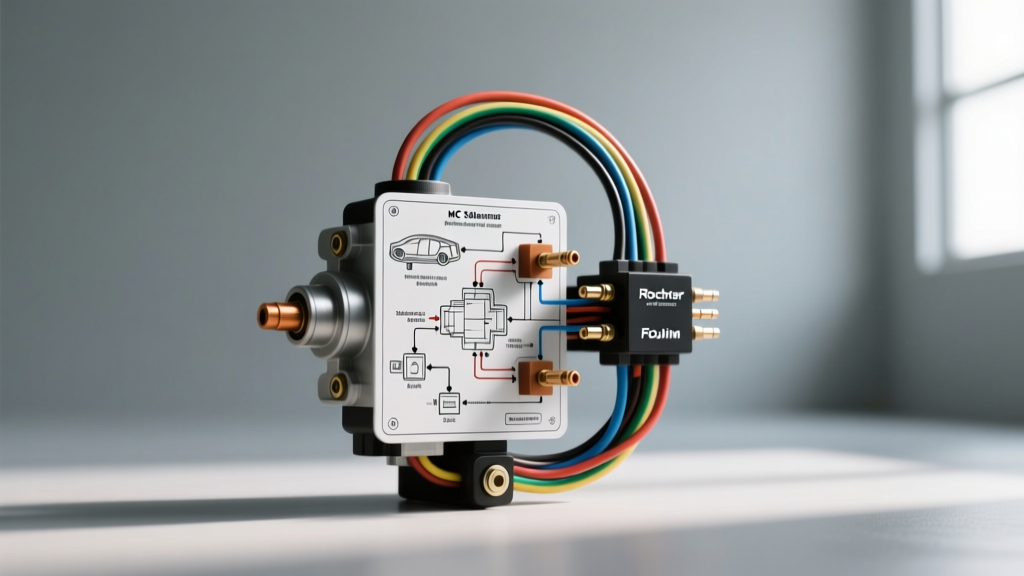
Understanding the Electronic Feedback Carburetor Wiring Diagram
While modern vehicles rely on high-pressure electronic fuel injection, the transitional era of the late 1970s through the mid-1980s introduced the electronic feedback carburetor. The most prominent example is the General Motors Computer Command Control (CCC) system, which utilized the Rochester Quadrajet E4ME electronic carburetor. To meet early emissions standards, GM integrated a Mixture Control (MC) solenoid, an Idle Air Bleed valve, and a Throttle Position Sensor (TPS) directly into the carburetor body, all managed by an early Engine Control Module (ECM).
Diagnosing driveability issues on these systems requires a deep understanding of the carburetor wiring diagram. Unlike simple 12-voltage mechanical chokes, feedback carburetors rely on pulse-width modulation (PWM) and 5-volt reference signals. A single corroded pin in a Weather-Pack connector or a frayed 18 AWG signal wire can force the ECM into open-loop operation, resulting in severe rich or lean drivability conditions. This guide provides a definitive, step-by-step troubleshooting flow for the primary circuits found in the Rochester feedback carburetor wiring diagram.
OEM Wire Color Codes and Connector Pinouts
The GM CCC system utilizes specific Delphi Weather-Pack connectors to seal the engine bay environment away from the sensitive ECM signals. Below is the standard pinout and wire gauge specification for the primary E4ME carburetor harness.
| Component | Wire Color | AWG | Connector Type | Circuit Function |
|---|---|---|---|---|
| Mixture Control (MC) Solenoid | Green / Black | 18 AWG | 2-Pin Weather-Pack | PWM Fuel Metering Signal / Ground |
| Idle Air Bleed Valve | Brown / Black | 18 AWG | 2-Pin Weather-Pack | PWM Air Metering Signal / Ground |
| Throttle Position Sensor (TPS) | Dark Blue / Black / Light Blue | 18 AWG | 3-Pin Weather-Pack | 5V Reference / Ground / Signal Return |
| Choke Heater Element | Pink / Black | 14 AWG | 2-Pin Spade/Pack | 12V Switched Ignition / Ground |
Note: Wire colors may vary slightly depending on the specific model year and chassis (e.g., Chevy C10 vs. Pontiac Firebird), but the circuit topology remains identical across the CCC platform. Always verify against the specific vehicle's factory service manual.
Step-by-Step Troubleshooting Flow: Mixture Control (MC) Solenoid
The MC solenoid is the heart of the feedback carburetor. It pulses at a fixed frequency of 10 Hz, varying the duty cycle (on-time vs. off-time) to adjust the primary metering rods. If your engine is running excessively rich or lean and the ECM is stuck in open-loop, follow this diagnostic tree.
Step 1: Verify Power and Ground at the Harness
Disconnect the 2-pin Weather-Pack connector at the MC solenoid. Turn the ignition to the 'ON' position (engine off). The ECM provides a 12-volt supply to the Green wire internally, switching the ground path to activate the solenoid. However, for testing purposes, we first verify the integrity of the Black ground wire.
- Test: Set your Digital Multimeter (DMM) to DC Volts.
- Procedure: Probe the Black wire terminal at the harness connector and connect the negative lead to a known good engine block ground.
- Specification: You should read 0.00V. If you read battery voltage (12V), the ground circuit is open. Perform a voltage drop test across the Black wire; a drop greater than 0.1V indicates high resistance or corrosion in the ECM ground splice.
Step 2: Measure Solenoid Coil Resistance
Electromagnetic coils degrade over time due to heat cycling, leading to internal shorts or opens. According to Delphi Powertrain Technologies, the internal coil must meet strict resistance thresholds to ensure the ECM driver transistor is not overloaded.
- Test: Set DMM to Ohms (Ω).
- Procedure: Probe the two terminals directly on the carburetor's MC solenoid (component side, not harness side).
- Specification: The resistance must be between 4.0 and 6.0 ohms at room temperature (68°F/20°C).
- Failure Mode: A reading of OL (Open Loop) indicates a broken internal winding. A reading below 3.0 ohms indicates a shorted coil, which will often blow the ECM's internal MC solenoid driver, requiring ECM replacement.
Step 3: Analyze the ECU Duty Cycle Signal
If resistance and grounds are verified, the ECM must be commanded to 'Closed Loop' operation (coolant temp above 100°F, O2 sensor active). You cannot test this with a standard voltmeter; you need an oscilloscope or a DMM with a Duty Cycle function.
- Test: Connect the DMM to the Green wire using a back-probe to maintain the weather seal.
- Specification: The signal should oscillate at 10 Hz. The duty cycle should hover around 50% at steady cruise, dropping to 20% (lean) or rising to 80% (rich) in response to O2 sensor feedback.
- Diagnostic Conclusion: If the signal is a steady 12V or 0V, the ECM is in open-loop mode. Check the coolant temperature sensor (CTS) and O2 sensor circuits before condemning the carburetor.
Troubleshooting the Throttle Position Sensor (TPS) Circuit
The TPS informs the ECM of throttle plate angle, dictating acceleration enrichment and idle air bleed strategies. A faulty TPS wiring diagram connection often manifests as a severe hesitation or 'flat spot' off idle.
- Verify 5V Reference: Back-probe the Dark Blue wire. With the key ON, engine OFF, you must read exactly 4.8V to 5.1V. If missing, trace the 5V reference line back to the ECM, checking for shorts to ground in the engine harness.
- Verify Ground: Back-probe the Black wire. Voltage drop to the battery negative terminal must be less than 0.05V.
- Sweep the Signal: Back-probe the Light Blue signal wire. Slowly open the throttle from idle to Wide Open Throttle (WOT). The voltage must sweep smoothly from approximately 0.45V (idle) to 4.50V (WOT).
- Identify Dead Spots: If the voltage jumps, drops out, or shows infinite resistance at any point during the sweep, the internal carbon wiper track is worn. Replace the TPS and recalibrate the idle voltage to factory spec using a feeler gauge.
Diagnosing the Idle Air Bleed Valve Circuit
The Idle Air Bleed valve operates similarly to the MC solenoid but meters air rather than fuel, controlling the idle mixture. Its internal coil resistance is significantly higher. When referencing the carburetor wiring diagram, ensure you do not swap the Brown (Air Bleed) and Green (MC Solenoid) harness connectors. While they are identical 2-pin Weather-Packs, swapping them will result in immediate driveability failure and potential ECM damage.
- Resistance Spec: 18.0 to 22.0 ohms.
- Acoustic Test: With the engine idling in closed-loop, you should hear a distinct, rapid 'buzzing' sound from the air horn of the carburetor. This is the 10 Hz PWM signal actuating the air bleed valve. Silence indicates a wiring fault, blown ECM driver, or seized valve pintle.
Weather-Pack Connector Degradation and Repair
The most common failure point in any vintage carburetor wiring diagram is the connector itself. The Delphi Weather-Pack system relies on silicone seals to block moisture. However, decades of engine heat cause the rubber seals to flatten and the nylon locking tangs to become brittle.
When repairing 18 AWG sensor wires, avoid soldering. Soldered joints create rigid points that concentrate vibrational stress, leading to wire fatigue and breakage inside the loom. Instead, adhere to the SAE J1128 Low Tension Primary Cable Standard by using open-barrel, ratcheting crimp tools specifically designed for Weather-Pack terminals. Always apply a small amount of dielectric grease to the terminal mating surfaces before reassembling the connector halves to prevent galvanic corrosion between the copper wire and the tin-plated brass terminal.
Summary of Diagnostic Best Practices
Troubleshooting a feedback carburetor requires treating the mechanical fuel system and the electrical wiring diagram as a single, unified ecosystem. Always verify the mechanical health of the carburetor—such as float level, choke pull-off, and base gasket vacuum leaks—before diving into deep electrical diagnostics. A vacuum leak will force the MC solenoid to its maximum rich limit, mimicking an electrical short. By methodically following this step-by-step flow, verifying AWG appropriateness, and respecting OEM pinout configurations, you can accurately diagnose and restore the closed-loop efficiency of these classic electronic carburetors.
Authoritative References: