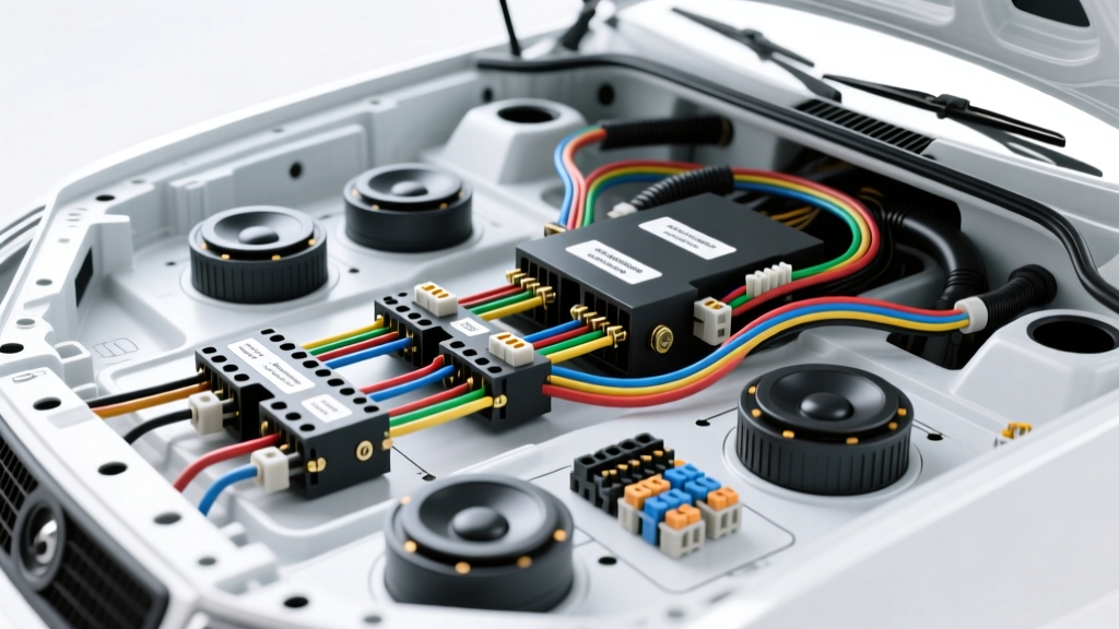
Introduction to the Automotive Speaker Wiring Diagram Series
When interpreting a speaker wiring diagram series for complex multi-channel automotive audio systems, technicians must look far beyond simple positive and negative connections. Modern vehicle audio architecture requires a deep understanding of electrical impedance, voice coil topology, and Original Equipment Manufacturer (OEM) harness integration. Whether you are upgrading a factory Bose or Harman Kardon system or building a custom competition-level SPL vehicle, the way you route and terminate your speaker wires dictates both acoustic performance and electrical safety.
In this advanced technical deep dive, we will dissect the physics of series and parallel speaker configurations, analyze standard EIA wire color codes, and outline the precise AWG requirements for high-current mobile audio environments. By mastering these schematic principles, you can prevent amplifier thermal rollback, eliminate phase cancellation, and ensure long-term reliability in harsh automotive conditions.
The Physics of Series vs. Parallel in Vehicle Audio
Unlike home audio, where amplifiers typically handle stable 8-ohm loads, car audio amplifiers are engineered to drive low-impedance environments, often dipping to 2 ohms or even 1 ohm per channel. Understanding how to manipulate these loads using a series or parallel topology is critical.
Series Wiring Topology
In a series circuit, the negative terminal of the amplifier connects to the positive terminal of the first speaker, the negative of the first speaker connects to the positive of the second, and finally, the negative of the second speaker returns to the amplifier's negative terminal. The total impedance is the sum of the individual speaker impedances:
Z_total = Z1 + Z2 + ... + Zn
For example, wiring two 4-ohm midrange drivers in series yields an 8-ohm load. While this reduces the current draw and heat generated by the amplifier, it also halves the output wattage on most solid-state Class AB or Class D mobile amplifiers. Series wiring is rarely used for main cabin speakers but is highly relevant when wiring Dual Voice Coil (DVC) subwoofers to achieve a specific target impedance.
Parallel Wiring Topology
Parallel wiring connects all positive terminals together and all negative terminals together. The formula for total impedance is:
1/Z_total = 1/Z1 + 1/Z2 + ... + 1/Zn
Two 4-ohm speakers wired in parallel result in a 2-ohm load. This is the standard configuration for maximizing RMS wattage from a monoblock subwoofer amplifier, provided the amplifier is rated for 2-ohm stability according to CEA-2006 standards.
OEM Harness Integration and Wire Color Codes
Integrating aftermarket DSPs (Digital Signal Processors) or amplifiers with factory head units requires tapping into the OEM speaker harness. Most aftermarket integrators rely on the EIA RS-773 standard for automotive speaker wire color coding. However, European vehicles (BMW, Audi, Mercedes-Benz) frequently deviate from this standard, utilizing proprietary MOST bus networks or specific pinouts documented in factory service manuals.
For standard aftermarket harnesses and domestic/Japanese OEM conversions, the following color codes apply:
| Channel | Positive Wire (+) | Negative Wire (-) | Common OEM Connector Type |
|---|---|---|---|
| Left Front | White | White w/ Black Stripe | Molex MX150 / Toyota Sumitomo |
| Right Front | Gray | Gray w/ Black Stripe | Molex MX150 / Nissan Yazaki |
| Left Rear | Green | Green w/ Black Stripe | TE Connectivity AMP |
| Right Rear | Purple | Purple w/ Black Stripe | TE Connectivity AMP |
Note: Always verify pinouts with a digital multimeter (DMM) before cutting or splicing. Factory amplified systems often utilize balanced differential audio signals rather than standard single-ended ground-referenced signals. Tapping into a differential signal incorrectly will result in severe distortion and potential damage to the OEM audio module.
AWG Specifications and Conductor Materials
Automotive environments subject wiring to extreme temperature fluctuations, vibration, and moisture. According to SAE J1128 standards for low-tension primary cables, wire insulation must withstand under-hood and under-dash thermal loads. For speaker runs, standard PVC insulation is generally sufficient for cabin use, but cross-linked polyethylene (XLPE) like GXL wire is recommended for runs passing through the firewall or engine bay.
Furthermore, the conductor material is paramount. Oxygen-Free Copper (OFC) is the only acceptable standard for high-fidelity car audio. Copper-Clad Aluminum (CCA) wire has a higher resistance per foot and is prone to galvanic corrosion and brittle fracture at crimp points due to vehicle vibration.
| Application | Recommended AWG (OFC) | Max Current (Amps) | Typical Run Length |
|---|---|---|---|
| Tweeters / High-Pass | 18 AWG | 5A - 8A | < 6 feet |
| Door Midrange / 6.5" Coaxial | 16 AWG | 10A - 15A | 8 - 12 feet |
| Component Midbass / High Power | 14 AWG | 15A - 25A | 12 - 18 feet |
| Subwoofers (Internal Box) | 12 AWG to 10 AWG | 30A+ | < 4 feet |
Executing a Series-Parallel Subwoofer Configuration
One of the most common scenarios requiring a complex speaker wiring diagram series is managing multiple DVC subwoofers. Suppose you have two 12-inch DVC 4-ohm subwoofers and a monoblock Class D amplifier rated for 2,000 Watts RMS at 2 ohms.
- Step 1 (Series per Subwoofer): Wire the positive terminal of Voice Coil A to the negative terminal of Voice Coil B on the first subwoofer. This puts the two 4-ohm coils in series, creating an 8-ohm load for that specific subwoofer.
- Step 2 (Repeat): Perform the exact same series jumper on the second subwoofer.
- Step 3 (Parallel to Amplifier): Connect the remaining positive terminal of Sub 1 and Sub 2 together, and run them to the amplifier's positive terminal. Connect the remaining negative terminals together and run them to the amplifier's negative terminal.
- Result: You now have two 8-ohm loads wired in parallel. Using the parallel formula, 8 / 2 = 4 ohms. Wait, this yields 4 ohms, not 2 ohms.
Correction for 2-Ohm Target: To achieve a 2-ohm load with two DVC 4-ohm subs, you must wire all four voice coils in parallel. Connect all positive terminals together and all negative terminals together. (4 ohms / 4 coils = 1 ohm). If the amp is only 2-ohm stable, you must use two DVC 2-ohm subwoofers wired in series-parallel (coils in series per sub = 4 ohms; subs in parallel = 2 ohms). Always verify the voice coil resistance with a DMM before finalizing the enclosure wiring.
Advanced Troubleshooting: Phase and Impedance Drops
Even with a perfect schematic, physical installation variables can introduce faults. Use this diagnostic tree to resolve common post-installation anomalies:
- Symptom: Weak mid-bass response and hollow vocal reproduction.
- Cause: Acoustic phase cancellation (comb filtering) due to reversed polarity on one speaker.
- Fix: Use a 9V battery to physically test cone excursion. Momentarily touch the positive battery terminal to the positive wire. If the cone pulls inward instead of pushing outward, the wiring is reversed. Alternatively, utilize a DSP's built-in polarity check or an RTA (Real-Time Analyzer) microphone to measure the impulse response.
- Symptom: Amplifier enters protection mode during high-volume bass transients.
- Cause: Impedance drop below the amplifier's minimum threshold. Voice coil resistance increases with heat, but mechanical binding or a shorted crossover capacitor can cause sudden drops.
- Fix: Measure the DMM resistance at the amplifier's speaker terminals while the vehicle is running. If the reading fluctuates wildly or drops below 1.5 ohms on a 2-ohm stable amp, inspect the speaker tinsel leads for fraying and test the passive crossover network for blown capacitors.
Termination and Connection Integrity
The weakest point in any automotive speaker wiring diagram series is the physical connection. T-taps and scotch locks are strictly prohibited in professional mobile electronics. They pierce the wire insulation, exposing the copper to oxidation and creating a high-resistance bottleneck that degrades the damping factor of the amplifier.
For OEM harness integration, utilize vehicle-specific wiring resources to identify the correct Molex or TE Connectivity pins. Use a proper terminal extraction tool to remove the factory pin, crimp a new Deutsch or Molex terminal onto your 16 AWG OFC wire, and reinsert it into the connector housing. If splicing is unavoidable, use the Western Union splice method, solder the joint with rosin-core solder, and seal it with adhesive-lined marine-grade heat shrink tubing. This prevents moisture ingress from door panels and ensures the connection will outlast the vehicle itself. For comprehensive wire routing and color code verification, always consult the Consumer Technology Association (CTA) mobile electronics guidelines alongside factory service manuals.