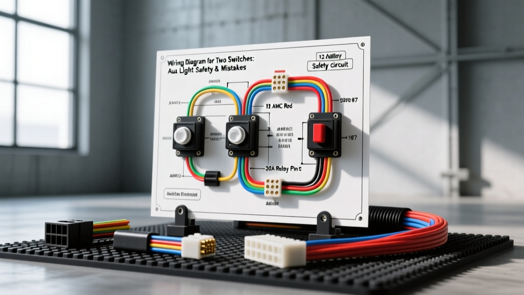
The Anatomy of a Dual-Switch Auxiliary Circuit
When outfitting an overland truck or off-road SUV with auxiliary lighting, enthusiasts frequently require independent control over multiple circuits. Searching for a reliable wiring diagram for two switches usually leads to basic schematics that omit critical safety protocols, voltage drop calculations, and relay isolation techniques. Whether you are wiring a roof rack light bar and a pair of bumper pods, or setting up a dual-solenoid winch controller, treating the two circuits as completely isolated systems is paramount for vehicle safety.
At the core of any high-amperage automotive accessory setup is the standard ISO mini relay (commonly referred to as a Bosch-style relay). A proper dual-switch configuration utilizes two separate 40A SPST (Single Pole, Single Throw) relays. The low-amperage trigger circuit routes from the cab switches to the relay coils (Pins 85 and 86), while the high-amperage load circuit routes from the battery distribution block, through the relays (Pins 30 and 87), to the auxiliary lights.
Trigger vs. Load Circuit Isolation
The most fundamental rule when interpreting a wiring diagram for two switches is maintaining strict isolation between the trigger circuit and the load circuit. The trigger circuit should utilize 18 AWG or 16 AWG primary wire, drawing less than 2 amps total for both relay coils. The load circuit, however, must handle the combined amperage of your lighting arrays, requiring 12 AWG, 10 AWG, or even 8 AWG wire depending on the total wattage and run length.
Top 5 Catastrophic Wiring Mistakes in Dual-Switch Setups
Even experienced DIYers make critical errors when scaling up from a single-switch harness to a dual-switch configuration. Based on forensic analysis of vehicle electrical fires and field failures, here are the most common mistakes to avoid.
1. The 'Daisy-Chain' Grounding Fallacy
When wiring two switches on a dashboard rocker panel, many installers daisy-chain the ground wire from Switch 1 to Switch 2, and then to a single chassis ground. This creates a ground loop and introduces variable resistance. If the single ground point vibrates loose or corrodes, both switches fail, or worse, the current backfeeds through the switch illumination LEDs, causing phantom voltage and switch overheating. The Fix: Use a dedicated ground bus bar behind the dash. Run individual 18 AWG ground wires from each switch to the bus bar, and ground the bus bar to the chassis using a ring terminal secured to bare, unpainted metal with a star washer.
2. Swapping Pin 87 and Pin 87a on High-Draw Loads
Standard 5-pin automotive relays feature Pin 87 (Normally Open) and Pin 87a (Normally Closed). The wiring diagram for two switches must explicitly route the high-amperage load through Pin 87. Pin 87a is mechanically designed for lower-amperage signaling and utilizes a thinner internal contact bridge. Routing a 30A lighting load through Pin 87a will cause the internal contacts to arc, weld together, and potentially melt the relay housing, leaving your auxiliary lights permanently on even when the switches are off.
3. Incorrect Fuse Placement and Sizing
According to SAE J1128 standards for low-tension primary cable, overcurrent protection must be placed as close to the power source as possible. A frequent mistake is placing the main 40A ATC fuse near the relays in the engine bay, leaving 8 feet of unfused 10 AWG wire running directly from the battery. If this wire chafes against the radiator support, it will ignite before the fuse blows. The Fix: Install an in-line ANL or Class T fuse holder within 18 inches of the positive battery terminal for the main power feed, and use secondary ATC fuses at the relay distribution block for individual circuit protection.
4. Ignoring Voltage Drop in Long Cab Runs
Auxiliary switches are often mounted in the cab, requiring long wire runs through the firewall to the engine bay relays. While 18 AWG wire is sufficient for short relay pigtails, a 15-foot run from the battery to the dash and back to the engine bay can suffer from severe voltage drop, resulting in weak relay coil engagement and audible 'chattering' of the relay contacts. Always upsize the trigger wire to 14 AWG or 12 AWG for firewall passes exceeding 10 feet.
5. Using T-Tap (Scotchlok) Connectors
T-tap connectors pierce the wire insulation and rely on a small metal blade to make contact. In the high-vibration, high-moisture environment of a vehicle chassis, these connectors are guaranteed to fail. They invite galvanic corrosion and moisture ingress, leading to high resistance and voltage drops. As recommended by Haynes Automotive Electrical Manuals, always use adhesive-lined marine-grade heat shrink butt splices, or solder connections sealed with dual-wall heat shrink.
Wire Gauge and Amperage Specification Chart
Refer to this chart when selecting wire for your dual-switch load circuits. These ratings are based on a 12V DC automotive system with a maximum allowable voltage drop of 3% (0.36V) for continuous loads.
| Total Load Amperage | Wire Length (One Way) | Minimum AWG Size | Recommended Fuse Size | Typical Application |
|---|---|---|---|---|
| 10A - 15A | Under 10 Feet | 14 AWG | 15A ATC | Single LED Pod (20W-40W) |
| 10A - 15A | 10 - 20 Feet | 12 AWG | 15A ATC | Dual LED Pods (Roof Rack) |
| 20A - 30A | Under 10 Feet | 12 AWG | 30A ATC | Small Light Bar (30-inch) |
| 20A - 30A | 10 - 20 Feet | 10 AWG | 30A ATC | Large Light Bar (50-inch) |
| 35A - 50A | Under 15 Feet | 8 AWG | 50A ANL | Heavy Winch Solenoid / Dual High-Draw Arrays |
Advanced Safety: Relay Coil Suppression (Flyback Diodes)
When wiring modern vehicles equipped with CAN-bus systems or Body Control Modules (BCM), triggering a relay directly from a factory switch circuit can cause severe electrical damage. When the switch is opened and the relay coil (Pins 85/86) is de-energized, the collapsing magnetic field generates a high-voltage reverse spike known as flyback voltage. This spike can arc across your dashboard switch contacts or instantly destroy a sensitive solid-state BCM output.
To prevent this, integrate a flyback suppression diode (such as a standard 1N4001 or 1N4004 rectifier diode) across the relay coil terminals. The diode must be installed in reverse bias (the silver stripe on the diode faces the positive 12V trigger source). This provides a safe recirculation path for the collapsing magnetic energy, protecting your vehicle's computers and extending the life of your mechanical switches. For a comprehensive guide on automotive relay specifications and coil suppression, refer to the Littelfuse Automotive Relays engineering documentation.
Connector Selection for the Engine Bay
The environment under the hood dictates the failure rate of your wiring diagram for two switches. Standard spade terminals on ISO relays are prone to oxidation and vibrating loose over corrugated terrain. For the load side of the relays (Pins 30 and 87), upgrade to sealed connector systems. The Deutsch DT series (2-pin or 4-pin) connectors utilize solid copper crimp pins with silicone rear seals and a positive locking wedge. Alternatively, the Delphi Metri-Pack 280 series is excellent for high-current automotive applications. Never rely on standard vinyl-insulated crimp terminals in the engine bay; they will wick moisture into the wire strands via capillary action, leading to hidden green corrosion and eventual open-circuit failures.
Diagnostic Checklist for Dual-Switch Failures
If your dual-switch setup is malfunctioning, follow this systematic diagnostic tree before replacing components:
- Step 1: Verify Main Power. Use a digital multimeter (DMM) to check for 12.6V at the input side of the main ANL fuse, and then at the output side. If voltage drops across the fuse holder, the crimps are loose or corroded.
- Step 2: Check Relay Pin 30. Probe Pin 30 on both relays. Both should read battery voltage. If one is dead, check the distribution block or splitter.
- Step 3: Test the Trigger Circuit. Turn Switch 1 ON. Probe Pin 86 on Relay 1. You should read within 0.5V of battery voltage. If you read 0V, the break is between the switch and the relay. If you read 8V, you have a high-resistance ground on the switch or a voltage drop due to undersized wire.
- Step 4: Verify the Ground Path. Probe Pin 85 on Relay 1 with the switch ON. It should read near 0V (ground). If it reads 12V, the ground wire to the chassis is severed or the ring terminal is attached to paint.
- Step 5: Load Test the Output. If the relay clicks but the lights do not turn on, probe Pin 87. If Pin 87 has 12V but the lights are dark, the failure is in the wiring harness leading to the lights, or the lights themselves have failed. Perform a voltage drop test across the ground wire of the light fixture to confirm chassis ground integrity.
Conclusion
Executing a flawless wiring diagram for two switches requires more than just connecting wires to terminals; it demands an understanding of automotive electrical physics, thermal limits, and environmental hazards. By isolating your trigger and load circuits, utilizing proper overcurrent protection near the battery, and abandoning cheap T-tap connectors in favor of sealed, adhesive-lined terminations, you ensure that your auxiliary systems operate reliably in the harshest off-road conditions. Always prioritize wire gauge sizing based on total run length, and never underestimate the destructive potential of an unfused power wire in a vehicle chassis.