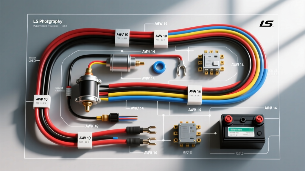
Introduction to LS Starter Circuit Architecture
The General Motors LS engine family (Gen III and Gen IV) remains the undisputed king of engine swaps and OEM restorations. However, when integrating an LS engine into a classic chassis or building a dedicated track car, the starter circuit is frequently treated as an afterthought. This leads to catastrophic failure modes, including severe voltage drop, intermittent cranking, and solenoid heat soak. Understanding the LS starter wiring diagram from a cost and tooling perspective is essential for fabricating a reliable, high-amperage starting circuit that will survive the harsh environment of an engine bay.
This technical analysis breaks down the exact material costs, mandatory tooling requirements, and precise wiring schematics needed to properly wire an LS starter, whether you are using an early LS1 PG260 starter or a later Denso-style gear-reduction unit.
Decoding the LS Starter Wiring Diagram
The foundational LS starter schematic relies on two primary circuits: the high-amperage Battery (BAT) feed and the low-amperage Signal (S) trigger circuit. Unlike older Chevrolet small-block starters that utilized a secondary 'R' terminal to bypass the ballast resistor during cranking, the LS ignition system is managed entirely by the PCM, eliminating the need for the 'R' terminal.
- BAT Terminal (B+): Receives direct, fused or unfused high-amperage current from the battery positive post. This terminal powers the starter motor and the solenoid pull-in coil.
- S Terminal (Signal): Receives a 12V trigger signal from the ignition switch, typically routed through a PCM-controlled crank relay (especially in Drive-By-Wire LS swaps to prevent crank-during-run conditions). This energizes the solenoid hold-in coil, engaging the Bendix drive with the flexplate.
Essential Tooling Requirements for LS Wiring
Fabricating custom battery cables and engine harnesses for an LS swap requires specialized automotive electrical tools. Relying on standard hardware store tools will result in high-resistance connections and premature failure.
Heavy-Duty Crimping and Torque Tools
- Ratcheting Hex-Crimp Tool (1/0 to 4 AWG): Standard hammer-style crimpers crush copper strands and create air pockets, leading to corrosion and voltage drop. A dedicated heavy-duty hex-crimp tool ensures a gas-tight, 360-degree compression on T2 copper ring terminals.
- Inch-Pound Torque Wrench: The solenoid nut on an LS starter is notoriously fragile. Over-torquing will crack the bakelite or composite solenoid housing, destroying the starter. An inch-pound torque wrench is mandatory for the BAT terminal nut.
- Digital Multimeter with Min/Max Hold: Essential for performing voltage drop testing across the BAT cable and the engine ground strap while the engine is under cranking load.
- Adhesive Heat Shrink & Heat Gun: Marine-grade, adhesive-lined heat shrink is required to seal the terminal barrel from engine bay moisture and prevent wicking corrosion into the copper strands.
Material Cost Breakdown: Wiring an LS Starter
Building a custom, high-quality LS starter harness from scratch is surprisingly cost-effective compared to buying pre-made, generic auto-parts store cables. Below is an accurate cost analysis for a professional-grade LS starter wiring setup.
| Component | Specification | Estimated Cost (USD) |
|---|---|---|
| Battery Cable (BAT Feed) | 1/0 AWG SAE J561 Copper (per ft.) | $6.50 - $8.00 |
| Ring Terminals | T2 Copper, 5/16" or 3/8" Stud | $1.50 each |
| Signal Wire (S Terminal) | 12 AWG TXL Primary Wire | $0.45 / ft. |
| Weather-Pack Connector | Delphi 1-Way Female (S Terminal) | $2.25 |
| High-Temp Loom | Fiberglass Silicone Sleeve (per ft.) | $4.00 |
| Adhesive Heat Shrink | 3M Marine Grade, Dual-Wall | $3.50 / pc |
| Total Estimated Material Cost | Complete Custom Harness | $25.00 - $40.00 |
Wire Gauge, Pinout, and Torque Specifications
Adhering to exact OEM and SAE specifications is critical when terminating the LS starter wiring diagram. The following table outlines the precise metrics for Gen III/IV starters.
| Terminal / Circuit | Wire Gauge (AWG) | OEM Wire Color | Terminal Type | Torque Specification |
|---|---|---|---|---|
| BAT (B+ Solenoid) | 1/0 AWG (or 1 AWG) | Red (Custom) / Black (OEM) | 3/8" or 5/16" Ring | 80 - 100 in-lbs (9 - 11 Nm) |
| S (Signal Trigger) | 12 AWG (TXL) | Purple | Female Spade / Metri-Pack | Hand Crimp (Pliers) |
| Engine Block Ground | 1/0 AWG | Black | 1/2" Ring to Block Bolt | 35 ft-lbs (Block Bolt) |
Advanced Troubleshooting: Heat Soak and Voltage Drop
Even with a perfect LS starter wiring diagram, the physical environment of the LS engine bay introduces unique electrical challenges. The passenger-side exhaust manifold sits mere inches from the starter solenoid, creating a massive thermal transfer issue.
Failure Mode 1: Solenoid Heat Soak
Symptom: The engine cranks perfectly when cold but fails to engage the starter after reaching operating temperature (common after a hot pit stop or traffic).
Cause: As the copper windings inside the starter solenoid absorb radiant heat from the exhaust, electrical resistance increases exponentially. The OEM 12 AWG S-terminal trigger circuit cannot supply enough amperage to overcome the high-resistance solenoid coil.
Wiring Fix (The Ford Solenoid Mod): Many LS swap fabricators bypass the OEM solenoid trigger by wiring a remote, heavy-duty Ford-style starter relay near the battery. Modified Diagram Logic: Battery Positive -> 1/0 AWG to Ford Relay Input. Ford Relay Output -> 1/0 AWG directly to the LS starter BAT terminal. A heavy-gauge jumper wire is installed directly between the BAT terminal and the S terminal on the LS starter. The OEM 12 AWG Purple S-terminal wire is now routed to the trigger post of the Ford relay. This reduces the S-terminal draw from ~40 amps to under 5 amps, entirely eliminating heat-soak cranking failures.
Failure Mode 2: Voltage Drop on the Ground Side
Symptom: Slow cranking RPMs, clicking relays, or PCM resetting during crank.
Cause: The LS starter grounds through its aluminum nose cone to the aluminum engine block. If the block mating surface is painted, powder-coated, or heavily oxidized, the starter lacks a ground path. Furthermore, relying on a small OEM ground strap is insufficient for high-compression LS engines.
Fix: Scrape the mounting surface of the engine block completely bare. Install a dedicated 1/0 AWG copper ground cable directly from the passenger-side cylinder head or block grounding boss to the vehicle chassis or battery negative. Test the circuit using a multimeter; a healthy LS starter circuit should show a maximum voltage drop of 0.10V across the ground side during cranking.
Authoritative References
- SAE J561: Battery Cable Standard - Society of Automotive Engineers. Defines the stranding, insulation, and amperacity requirements for heavy-duty battery cables used in the BAT terminal circuit.
- SAE J1128: Low Tension Primary Cable - Society of Automotive Engineers. Governs the TXL/GXL wire specifications required for the 12 AWG S-terminal signal wiring to ensure resistance to engine bay temperatures.
- Delphi Automotive Systems Connector Catalog - Reference for Weather-Pack and Metri-Pack terminal crimp profiles and pull-test specifications for the LS starter signal connectors.