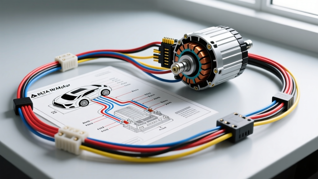
Introduction to Delta Configurations in Automotive Motors
When automotive technicians and DIY enthusiasts search for a delta wiring diagram for a motor, they are often looking at industrial 3-phase machinery. However, in the automotive world, 3-phase delta configurations are the hidden workhorses of modern vehicle electrical systems. You will not find a standard 3-phase induction motor under the hood of a gas-powered car, but you will find 3-phase delta-wound stators inside high-output alternators, as well as 3-phase delta-style power delivery networks in Electric Vehicle (EV) and Hybrid traction motors.
Understanding how to read, test, and troubleshoot a delta wiring diagram is a fundamental skill for diagnosing charging system failures, rebuilding alternators, or safely servicing high-voltage EV powertrains. This beginner-friendly guide bridges the gap between electrical theory and real-world automotive applications, providing the exact wire colors, AWG specifications, and diagnostic procedures you need.
The Anatomy of a Delta Wiring Diagram
In electrical engineering, a 'delta' (Δ) configuration refers to a polyphase system where the windings are connected end-to-end, forming a closed triangular loop. Unlike a 'Wye' (or Star) configuration, which features a common neutral center point, a delta system has no neutral wire. Instead, power is tapped directly from the three junction points (nodes) where the windings meet.
In an automotive context, this translates to three distinct phase leads—universally designated as U, V, and W—that carry the alternating current (AC) generated by the motor or alternator. Because the windings form a closed loop, the electrical characteristics differ vastly from Wye setups, prioritizing high current output over high voltage.
Automotive Application 1: High-Output Alternator Stators
Modern vehicles demand immense electrical power to run infotainment systems, electric power steering (EPS), and advanced driver-assistance systems (ADAS). To meet this demand, manufacturers like Bosch and Denso utilize delta-wound stators in their high-amp alternators.
Why Alternators Use Delta Over Wye
According to Autoshop101's Automotive Electrical Training Modules, a delta-wound stator can produce approximately 73% more maximum current than an identically sized Wye-wound stator. The trade-off is that a delta stator requires slightly higher engine RPMs to reach the 'cut-in' voltage required to begin charging the battery. Because modern engines idle higher and utilize decoupler pulleys, the delta configuration's high-current advantage makes it the industry standard for modern charging systems.
Alternator Stator Pinout & Wire Colors
When examining an alternator wiring diagram, the stator consists of heavy-gauge enameled copper wire bundled into three main phase leads. These leads connect directly to the rectifier assembly (diode bridge), which converts the 3-phase AC into DC for the vehicle's 12V system.
| Phase Node | Typical OEM Wire Color | Internal Wire Gauge (AWG) | Connection Point | Function |
|---|---|---|---|---|
| Phase U | Yellow (or Bare Copper) | 17 AWG - 19 AWG (Enameled) | Rectifier Diode Pack Node 1 | Carries Phase 1 AC to Positive/Negative Diodes |
| Phase V | Green (or Bare Copper) | 17 AWG - 19 AWG (Enameled) | Rectifier Diode Pack Node 2 | Carries Phase 2 AC to Positive/Negative Diodes |
| Phase W | Red (or Bare Copper) | 17 AWG - 19 AWG (Enameled) | Rectifier Diode Pack Node 3 | Carries Phase 3 AC to Positive/Negative Diodes |
Note: Many OEMs do not use colored insulation on the stator leads. Instead, they use bare, solder-dipped enameled copper wires that are resistance-welded directly to the rectifier pigtails to prevent heat-related connection failures.
Automotive Application 2: EV Traction Motor Inverter Cables
In Electric Vehicles (EVs) and Hybrids, the traction motor (usually a Permanent Magnet Synchronous Motor or PMSM) is driven by an inverter. The inverter converts high-voltage DC from the battery into 3-phase AC. While the internal windings of the motor may be Wye or Delta, the external wiring harness connecting the inverter to the motor casing operates on the same 3-phase delta topology principles, utilizing the U, V, and W designations.
High-Voltage Cable Specs & Torque Requirements
Servicing these cables requires strict adherence to safety protocols outlined by SAE International's EV Safety Guidelines (J2344). The cables are heavily shielded to prevent Electromagnetic Interference (EMI) and are universally color-coded orange to denote lethal high voltage.
| Phase | Cable Jacket Color | Conductor Size | Shielding | Terminal Torque Spec (Typical) |
|---|---|---|---|---|
| U-Phase | Orange (HV Standard) | 2 AWG to 35mm² | Braided Copper + Mylar Wrap | 15 Nm - 22 Nm (Verify OEM) |
| V-Phase | Orange (HV Standard) | 2 AWG to 35mm² | Braided Copper + Mylar Wrap | 15 Nm - 22 Nm (Verify OEM) |
| W-Phase | Orange (HV Standard) | 2 AWG to 35mm² | Braided Copper + Mylar Wrap | 15 Nm - 22 Nm (Verify OEM) |
Pro-Tip: When reinstalling EV phase cables, always apply torque paint (witness marks) across the nut and terminal stud after torquing. This allows for rapid visual inspection during future service intervals to ensure vibration has not backed off the high-current lugs.
Step-by-Step Troubleshooting: Testing Delta Windings
Testing a delta-wound motor or alternator stator requires a different diagnostic approach than a Wye-wound system. Because the windings form a closed triangle, measuring resistance across any two terminals does not just measure one winding; it measures one winding in parallel with the series combination of the other two.
The 'Two-Thirds' Resistance Rule
If all three windings in a delta configuration have an identical resistance of R, a multimeter placed across any two nodes (e.g., U and V) will read 2/3 of R. Understanding this mathematical reality prevents technicians from falsely condemning good components.
DMM Diagnostic Procedure (Alternator Stator)
- Isolate the Component: Remove the alternator from the vehicle. Desolder or unbolt the three stator leads from the rectifier diode pack to isolate the raw copper windings.
- Set the Multimeter: Set your Digital Multimeter (DMM) to the lowest Ohms (Ω) setting, or the dedicated continuity setting.
- Measure Phase-to-Phase: Place probes on U-V, then V-W, then U-W.
- Interpret the Data:
- Normal: All three readings are identical and very low (typically 0.1Ω to 0.5Ω for automotive stators).
- Open Winding: If one winding is broken internally, the two nodes spanning that break will read a significantly higher resistance (the series resistance of the remaining two windings, or 2R), while the third pair will read normal. If the break is total, your DMM will read 'OL' (Open Loop).
- Shorted Winding: If one reading is significantly lower than the other two, or reads 0.00Ω, the enameled insulation inside the stator core has melted, causing an inter-turn short. The stator must be replaced.
- Ground Fault Test: Set the DMM to Megaohms (MΩ). Place one probe on the bare stator iron core and the other on each phase lead (U, V, W). Any reading less than 10 MΩ indicates the winding is shorted to the chassis, which will cause severe battery drain and alternator whining.
Common Failure Modes in Automotive Delta Systems
Based on technical literature from Bosch Mobility Solutions, the most common failure point in a delta-wound alternator is not the copper wire itself, but the solder joints at the rectifier bridge. The extreme heat generated by the diodes during high-amperage charging (often exceeding 150°C locally) can cause lead-free solder to fatigue and crack over time. This results in an intermittent 'open' delta circuit, leading to a pulsing DC output that can confuse the vehicle's PCM and trigger a 'Battery Not Charging' code (e.g., P0620).
For EV traction motors, the primary failure mode involves the degradation of the orange HV cable shielding. If the braided copper shield is compromised by chassis chafing, high-frequency EMI can leak into the vehicle's CAN bus network, causing ghost codes, erratic sensor readings, and inverter shutdowns. Always inspect the full length of U, V, and W phase cables for abrasion when diagnosing unexplained EV drivetrain faults.
Summary
Whether you are rebuilding a 200-amp Denso alternator or diagnosing an inverter fault on a modern EV, mastering the delta wiring diagram for a motor is essential. By understanding the U-V-W phase topology, recognizing the 'two-thirds' resistance testing rule, and adhering to strict torque and safety specifications, you can confidently troubleshoot the most complex 3-phase systems in the automotive industry.