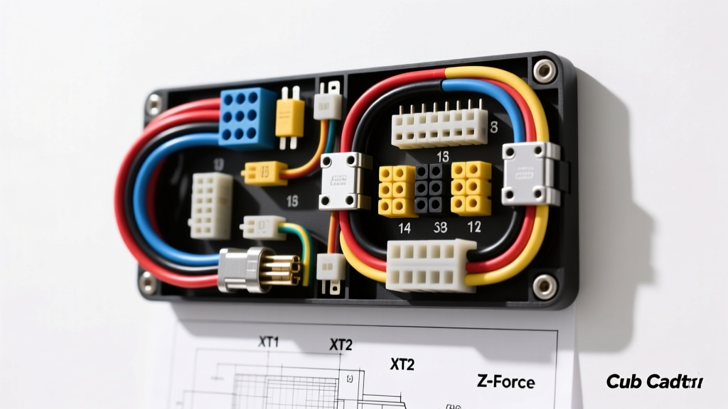
The Search for a Reliable Cub Cadet Wiring Diagram PDF Free Download
When your lawn tractor fails to crank, the PTO clutch refuses to engage, or the charging system leaves your battery dead, searching for a cub cadet wiring diagram pdf free download is the logical first step for any DIY mechanic. However, outdoor power equipment electrical systems are subjected to extreme vibration, moisture, UV degradation, and thermal cycling. Because MTD (Cub Cadet's parent company) produces dozens of chassis and engine variations across the Enduro, Z-Force, and Commercial lines, downloading a generic or mismatched schematic can lead to catastrophic short circuits or misdiagnosed components.
This comprehensive selection guide compares the electrical architectures of major Cub Cadet series, breaks down critical circuit specifications, and helps you identify exactly which wiring documentation and tracing methodology you need to safely repair your machine. Whether you are working on a single-cylinder XT1 or a twin-cylinder EFI Z-Force, understanding the underlying electrical logic is paramount.
Comparing Cub Cadet Electrical Architectures: Which Diagram Do You Need?
Before downloading any schematic, you must identify your tractor's specific electrical generation. Cub Cadet wiring harnesses have evolved significantly over the last decade, moving from simple point-to-point relay logic to integrated solid-state modules.
Enduro Series (XT1 & XT2) Lawn Tractors
The Enduro series utilizes a traditional, relay-heavy electrical architecture. The wiring harness is typically routed through a centralized safety interlock module that governs the starter solenoid and the PTO clutch relay. Diagrams for these models focus heavily on mechanical switch logic (seat switch, brake pedal switch, and PTO engagement switch). The stator output on these models usually ranges from 9 to 15 amps, requiring standard 14 AWG wiring for the charging circuit.
Z-Force & Commercial Zero-Turn Mowers
Zero-turn models feature significantly higher electrical loads. With the integration of Electronic Fuel Injection (EFI), digital dash displays, and high-output LED lighting kits, the Z-Force series relies on heavy-duty stators (up to 30A output) and solid-state voltage regulators. The wiring diagrams for these units are much more complex, often featuring CAN-bus communication lines between the engine control unit (ECU) and the dash display, requiring specialized pinout charts rather than simple line drawings.
Resource Selection Guide: OEM Manuals vs. Free PDF Repositories
Not all schematics are created equal. Blurry, third-party scans often omit critical ground points or relay pin numbers. Below is a comparison of where to source your documentation.
| Source Type | Pros | Cons | Best Used For |
|---|---|---|---|
| OEM Service Manuals (Dealer Portal) | High-resolution, includes pinout tables, torque specs, and diagnostic flowcharts. | Often requires a paid subscription or dealer access. | Complete harness rebuilds and ECU diagnostics. |
| Operator's Manual (Free PDF) | Easily found via free download; includes basic fuse box layouts and battery specs. | Lacks detailed wire color codes, AWG sizes, and interlock logic gates. | Battery replacement, fuse checking, and basic bulb swaps. |
| Third-Party PDF Repositories | Free access to older, out-of-warranty model schematics. | High risk of downloading the wrong model year; missing legend keys. | Legacy tractors (pre-2010) where OEM support is discontinued. |
Critical Circuit Breakdown: PTO Clutch & Safety Interlock Systems
The most common electrical failure on any Cub Cadet tractor involves the Power Take-Off (PTO) clutch circuit. When reviewing your downloaded wiring diagram, pay strict attention to the following specifications to ensure proper repair.
PTO Clutch Wiring Specifications
- Wire Color: Purple (12V+ switched to clutch), Black (Ground).
- Wire Gauge: 10 AWG. Expert Note: While the clutch only draws 2.5 to 4.0 amps, the physical distance from the battery/relay to the front-mounted clutch creates resistance. Using 14 AWG wire will cause a voltage drop, delivering only 10.5V to the coil. This results in clutch slippage, excessive heat, and premature burnout.
- Relay Type: 30A Bosch-style mini relay (usually located under the dash or near the battery box).
- Connector: 1/4-inch insulated female spade terminals with locking tangs, or Molex MX150 weather-sealed connectors on newer EFI models.
The Safety Interlock Logic Gate
Cub Cadet employs a strict safety interlock system to prevent the engine from cranking if the PTO is engaged, or to kill the engine if the operator leaves the seat with the blades spinning. In the wiring diagram, this is represented by a cascade of switches or a dedicated Interlock Control Module (ICM).
- Brake Pedal Switch: Normally Open (NO). Closes when the pedal is fully depressed.
- Seat Switch: Normally Closed (NC). Opens when the operator stands up.
- PTO Switch: Monitored by the ICM to ensure disengagement before cranking is permitted.
- Sense Wires: Typically White or Gray, 16 AWG. These carry low-amperage logic signals, not primary power.
Charging System: Stator and Rectifier/Regulator Diagnostics
Outdoor power equipment engines (commonly Kawasaki or Kohler) use a permanent magnet stator rather than an automotive-style alternator. The wiring diagram will show two or three Yellow wires exiting the engine block and routing to a finned Rectifier/Regulator module.
Diagnostic Specs: Before replacing a dead battery, use a multimeter to test the Yellow wires at the connector. With the engine running at 3600 RPM, you should read between 28V and 35V AC. If the AC voltage is correct but the battery is not charging, the rectifier is failing to convert the AC to the required 14.2V - 14.6V DC. Ensure the rectifier's grounding tab is bolted to clean, bare metal; a poor ground will cause the module to overheat and melt the plastic connector housing.
Troubleshooting Decision Tree: Tractor Will Not Crank
Use this structured troubleshooting path alongside your specific model's wiring diagram to isolate a no-crank condition without throwing unnecessary parts at the problem.
- Step 1: Check Battery Voltage
- Less than 12.4V? Charge battery and test stator output.
- Greater than 12.4V? Proceed to Step 2.
- Step 2: Bypass Solenoid
- Jump the two large posts on the starter solenoid with a screwdriver.
- Engine cranks? Solenoid or starter motor is good. Proceed to Step 3.
- Engine does not crank? Check main ground cable and starter motor.
- Step 3: Check Ignition Switch 'S' Terminal
- Turn key to START. Probe the small 'S' terminal on the solenoid.
- 12V present? Solenoid coil is internally faulty. Replace solenoid.
- No voltage? Proceed to Step 4 (Interlock Fault).
- Step 4: Trace Interlock Logic
- Verify brake pedal is fully depressed (switch continuity).
- Verify PTO switch is in the OFF position.
- Check the inline fuse (usually 20A or 30A) located between the ignition switch and the solenoid.
Authoritative References & Schematic Standards
When repairing or modifying your Cub Cadet harness, always adhere to established automotive and outdoor power equipment electrical standards. Splicing wires with electrical tape is unacceptable in high-vibration, high-moisture environments.
- Wire Gauge and Insulation: All primary wiring repairs should comply with SAE J1128 standards for low-tension primary cable, ensuring the insulation can withstand engine bay temperatures and chemical exposure.
- Connectors: For any exterior lighting or stator extensions, utilize Delphi Weather-Pack connectors. These feature silicone seals that prevent water intrusion and green corrosion on the brass terminals, a common failure point in standard Molex connectors used on older mowers.
- OEM Documentation: Always cross-reference your specific model and serial number via the Cub Cadet Official Manual Portal to ensure the safety interlock logic matches your exact production run, as mid-year harness revisions are common in the outdoor power industry.
By understanding the specific wire colors, AWG requirements, and logic gates detailed in your schematic, you can confidently diagnose and repair your Cub Cadet tractor, ensuring it operates safely and reliably for seasons to come.