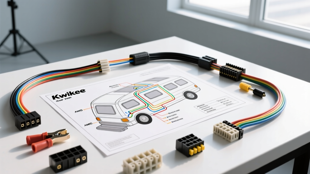
Introduction to Kwikee Electric Step Systems
For decades, Kwikee has been the industry standard for electric RV steps, outfitting thousands of motorhomes, travel trailers, and fifth wheels. Now a subsidiary of Lippert Components (LCI), the engineering behind Kwikee steps has evolved from simple relay-driven 4-wire motors to sophisticated solid-state control modules with integrated current sensing. Whether you are restoring a vintage Class A motorhome or troubleshooting a late-model Series 32 or Series 28 step assembly, having an accurate Kwikee step wiring diagram PDF is critical for safe and reliable operation.
Unlike standard automotive lighting circuits, RV step systems must handle high inductive loads, endure severe voltage drops over long chassis wire runs, and integrate seamlessly with vehicle ignition and door switch logic. This technical specification reference breaks down the exact wire color codes, AWG requirements, pinout configurations, and diagnostic procedures required to service Kwikee electric step systems according to NFPA 1192 Standard on Recreational Vehicles and OEM guidelines.
Understanding Kwikee Control Module Architectures
Before referencing a specific Kwikee step wiring diagram PDF, it is vital to identify which generation of control module your RV utilizes. Kwikee systems generally fall into two categories:
1. Legacy 4-Wire Motor Systems (Pre-2010)
Older Kwikee steps utilized a permanent magnet DC motor with four distinct brushes and leads. The control module (often a heavy relay box) switched polarity internally to reverse the motor direction. These systems required robust relay contacts and were prone to arcing and contact welding if the step encountered mechanical resistance.
2. Modern 2-Wire Reversible Motor Systems (Post-2010)
Modern Lippert/Kwikee systems utilize a 2-wire reversible motor paired with a smart solid-state control module (e.g., part number 909516000 or 151332). The control module uses H-bridge circuitry to reverse polarity electronically. This design reduces the wiring harness complexity between the motor and the controller, relying on a standardized 4-pin or 6-pin Weather-Pack or Deutsch connector for chassis integration.
Control Module Terminal Pinout Reference
The most common modern Kwikee control module utilizes a 4-pin chassis connector. Below is the definitive pinout specification for integrating the step controller with the RV’s 12V DC electrical system.
| Pin / Wire Color | Function | AWG Requirement | Signal Type / Logic |
|---|---|---|---|
| Red | 12V+ Battery Power | 10 AWG | Constant 12V DC (Fused 20A/30A) |
| White | System Ground | 10 AWG | Chassis Ground (0V) |
| Yellow | Magnetic Door Switch | 14 AWG or 16 AWG | Switched Ground / Logic Trigger |
| Brown | Ignition Override | 14 AWG or 16 AWG | 12V+ Active High (Prevents Deployment) |
Note: Motor leads (typically Black and Red, or two Black wires with a tracer) connect directly to the separate 2-pin motor plug on the control module, not the chassis harness.
Wire Gauge, Routing, and Voltage Drop Specifications
A frequent cause of Kwikee step failure is not a defective motor, but inadequate wire gauge leading to severe voltage drop. Because the step motor is typically located at the entry door—often 15 to 25 feet away from the house battery bank—wire resistance becomes a critical factor.
According to the SAE J1128 Low Tension Primary Cable Standard, stranded copper wire must be rated for under-hood and chassis temperatures. For Kwikee steps, the main power (Red) and ground (White) wires must be a minimum of 10 AWG. However, if the wire run from the battery to the control module exceeds 15 feet, you must upgrade to 8 AWG wire to maintain adequate voltage at the controller.
Voltage Drop Calculation for RV Steps
A Kwikee motor drawing 15 Amps over a 20-foot round-trip circuit using 10 AWG wire will experience a voltage drop of approximately 0.6V. While this seems negligible, if the RV’s house battery is already depleted to 11.5V, the voltage arriving at the control module will be 10.9V. Solid-state Kwikee control modules feature low-voltage lockout protection; if input voltage drops below 10.5V under load, the logic board will reset, causing the step to stutter, reverse unexpectedly, or fail to deploy.
- Runs under 10 feet: 10 AWG stranded copper
- Runs 10 to 18 feet: 8 AWG stranded copper
- Runs over 18 feet: 6 AWG stranded copper
Magnetic Door Switch and Ignition Override Logic
The Yellow and Brown wires dictate the operational logic of the Kwikee step, ensuring passenger safety and preventing catastrophic damage while the vehicle is in motion.
The Yellow Wire: Magnetic Reed Switch
The Yellow wire connects to the magnetic reed switch mounted on the RV entry door frame. In most modern Kwikee configurations, this is a Normally Open (NO) switch. When the door is closed, the magnet pulls the reed switch closed, completing the ground circuit on the Yellow wire. This signals the control module to retract the step. When the door opens, the circuit breaks, and the module deploys the step. Diagnostic Tip: If the step extends and retracts erratically, check the air gap between the door magnet and the reed switch. An air gap exceeding 3/8 inch will cause intermittent signal loss.
The Brown Wire: Ignition Override
The Brown wire is a critical safety feature designed to override the door switch and force the step to retract when the vehicle's engine is running. This wire must be tied to an ignition-switched 12V+ source (active only when the key is in the 'ON' or 'RUN' position). If the Brown wire receives 12V+, the control module will immediately retract the step and lock out the deployment circuit, regardless of the door switch position. Failure to wire the Brown override is a leading cause of step destruction on highways.
Advanced Electrical Troubleshooting and Amp Draw Testing
When consulting a Kwikee step wiring diagram PDF to diagnose a failure, technicians must differentiate between electrical faults and mechanical binding. The most effective method is performing an amp draw test using a DC clamp meter or an inline shunt.
Normal vs. Abnormal Amp Draw Signatures
- Normal Deployment/Retraction: 10A to 15A steady draw.
- Initial Startup Spike: Up to 25A for 0.5 seconds (normal inductive inrush).
- Mechanical Bind / Lack of Lubrication: Sustained draw of 20A to 30A, often accompanied by the motor stalling and the control module clicking (internal thermal or current-limit protection tripping).
- Short Circuit: Immediate >40A spike, blowing the main 20A or 30A automotive blade fuse.
Testing the Control Module Logic
If the motor tests correctly on a bench (applying direct 12V and reversing polarity to verify up/down function), the fault lies in the chassis wiring or control module. Use a digital multimeter (DMM) to back-probe the 4-pin connector:
- Verify 12.0V+ between the Red and White pins with the door open and closed.
- Verify the Yellow pin drops to near 0V (ground) when the door is closed, and floats to 12V when open.
- Verify the Brown pin reads 0V with the ignition off, and 12V+ with the ignition on.
If all logic signals are correct, the main power is stable, and the motor functions on direct power, the solid-state control module has suffered an internal H-bridge failure and must be replaced. For comprehensive OEM troubleshooting flowcharts and warranty information, refer to the Lippert Components RV Support Documentation.
Circuit Protection and Grounding Best Practices
Kwikee steps must be protected by a dedicated fuse or circuit breaker located within 18 inches of the positive battery terminal. A 20-Amp or 30-Amp automotive blade fuse (ATO/ATC) is standard, depending on the step series (e.g., heavy-duty Series 42 steps require 30A). Never tap the step power wire into an existing RV lighting or appliance circuit. The inductive kickback generated by the step motor can induce voltage spikes that will destroy sensitive LED drivers and RV control boards.
Finally, the White ground wire must be terminated to a clean, bare-metal chassis ground point or routed directly back to the negative bus bar. Relying on the step motor's mounting bolts for a return path is a violation of RV electrical codes and will inevitably lead to galvanic corrosion, high resistance, and module failure.