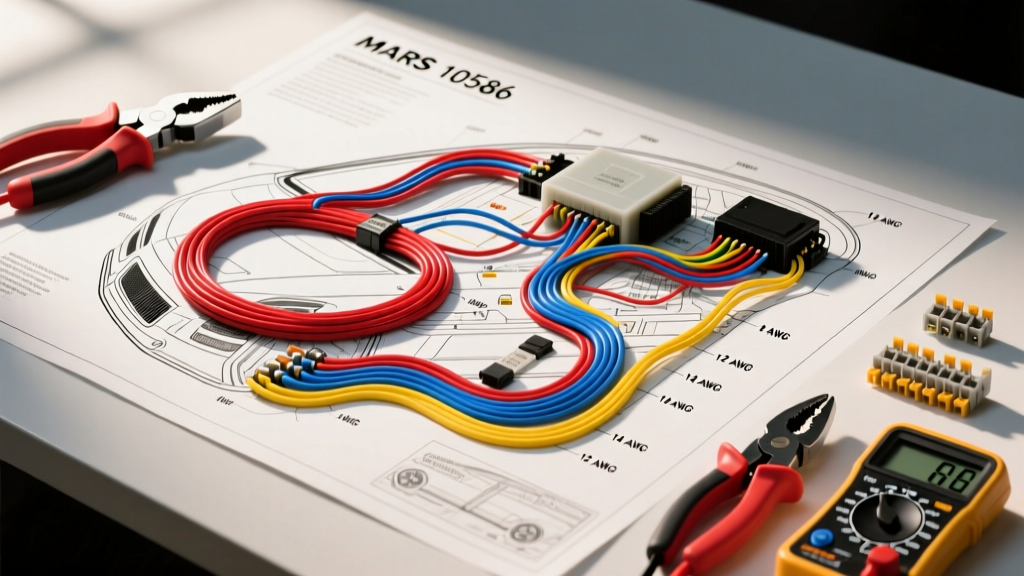
Introduction to the MARS 10586 in Mobile Platforms
The MARS 10586 is a heavy-duty, 2-pole, 30-amp definite purpose contactor featuring a 24V coil. While originally engineered for residential and commercial HVAC compressor circuits, expedition vehicle builders, custom RV fabricators, and heavy-duty 24V military truck mechanics frequently adapt this component for mobile applications. It is highly valued for switching high-amperage inductive loads such as auxiliary AC compressors, high-output winch solenoids, and dual-battery isolation systems. Because it bridges the gap between stationary refrigeration and mobile DC architectures, finding a dedicated automotive mars 10586 wiring diagram pdf can be challenging. This comprehensive analysis breaks down the exact costs, tooling requirements, and technical specifications necessary to integrate this contactor safely and reliably into a 12V or 24V mobile platform.
Sourcing the Mars 10586 Wiring Diagram PDF: Cost Breakdown
Unlike standard automotive relays, the MARS 10586 does not appear in standard OEM automotive service manuals (like Mitchell1 or ALLDATA) because it is an aftermarket HVAC component. Therefore, acquiring the correct schematic requires looking outside traditional automotive databases.
- Manufacturer Spec Sheets (Cost: $0): The most accurate wiring diagram is available directly from the MARS Definite Purpose Contactors technical library. These PDFs provide the exact terminal layout, coil resistance specs, and torque values.
- RV and Marine Wiring Repositories (Cost: $15 - $30): Specialized RVIA-certified wiring repositories often bundle HVAC contactor diagrams into broader RV AC repair manuals. Accessing these premium PDF databases typically requires a one-time purchase or a monthly subscription.
- HVAC Service Manuals (Cost: $40 - $60): If you are integrating the 10586 into a custom expedition camper's climate control system, purchasing the specific rooftop AC unit's service manual (e.g., Dometic or Coleman) will include the contactor wiring diagram in the context of the full system.
Tool Requirements for 30A Contactor Installation
Wiring a 30A continuous-load contactor in a high-vibration automotive environment requires professional-grade tools. Standard household electrical tools will result in poor crimps, leading to voltage drop, arcing, and eventual fires.
Wire Preparation and Crimping Tools
For the load-bearing terminals (L1/T1 and L2/T2), you must use 10 AWG wire. Stripping and crimping this gauge requires specialized equipment:
- Wire Strippers: A heavy-duty automatic stripper like the Titan 11477 or Knipex ErgoStrip is required to cleanly remove cross-linked polyethylene (GXL) insulation without nicking the copper strands.
- Ratcheting Crimper: Use an IWISS IWS-16 or Glarks ratcheting crimper designed for 12-10 AWG non-insulated or heat-shrink ring terminals. Ratcheting mechanisms ensure the terminal is compressed to the exact SAE J1128 pull-force specification before the tool releases.
- Heat Gun: A variable-temperature heat gun (e.g., Milwaukee M18 or Steinel) is mandatory for shrinking dual-wall adhesive heat shrink tubing, which creates a waterproof environmental seal crucial for under-hood or chassis-mounted applications.
Testing and Diagnostics Equipment
- Digital Multimeter (DMM): A Fluke 87V or equivalent True-RMS meter is necessary to measure the coil's DC resistance (typically 15-25 ohms for a 24V DC coil) and to check for voltage drop across the closed contacts under load.
- Clamp-On Ammeter: Required to verify that the inductive load does not exceed the 30A continuous rating during the initial compressor or motor startup surge (Locked Rotor Amps).
Bill of Materials and Cost Breakdown
Below is an estimated cost analysis for a professional-grade installation of the MARS 10586 in an automotive or RV environment. Prices reflect high-quality, marine/automotive-grade materials.
| Component | Specification | Est. Cost (USD) |
|---|---|---|
| MARS 10586 Contactor | 2-Pole, 30A, 24V Coil | $18.00 - $24.00 |
| Load Wire | 10 AWG GXL (10 ft) | $14.00 |
| Control Wire | 16 AWG SXL (10 ft) | $8.00 |
| Terminals | 10 AWG #10 Ring, 16 AWG 1/4' Spade | $15.00 |
| Environmental Sealing | Dual-Wall Adhesive Heat Shrink | $12.00 |
| 12V to 24V DC-DC Converter | 2A Step-Up (For 12V Chassis Integration) | $35.00 |
| Overcurrent Protection | 40A MIDI/AMEG Fuse & Holder | $18.00 |
| Total Estimated Cost | $120.00 - $126.00 |
Technical Wiring Specifications & Pin Configurations
The physical layout of the MARS 10586 is straightforward, but adherence to torque specifications and wire gauge limits is critical for mobile applications subject to thermal cycling and vibration.
Load Circuit (Power Side)
- Terminals: L1 and L2 (Line/Source), T1 and T2 (Load/Output).
- Wire Gauge: 10 AWG GXL (SAE J1128 compliant for under-hood temperatures up to 125°C).
- Terminal Type: #10 closed-ring, non-insulated with adhesive heat shrink.
- Torque Specification: 18 to 22 in-lbs. Under-torquing causes micro-arcing and carbon buildup; over-torquing strips the soft brass terminal threads.
- Protection: A 40A slow-blow MIDI fuse must be installed within 7 inches of the primary battery positive terminal feeding L1/L2.
Coil Circuit (Control Side)
- Terminals: Two 1/4-inch male quick-disconnect spades located on the electromagnetic coil housing.
- Wire Gauge: 16 AWG SXL.
- Current Draw: Approximately 0.8A to 1.2A during initial pull-in, dropping to a holding current of roughly 0.4A.
12V Automotive to 24V Coil Integration Strategy
The most common error when adapting the MARS 10586 for automotive use is ignoring the coil voltage. The 10586 features a 24V coil. If you connect this coil directly to a standard 12V automotive or RV chassis battery, the magnetic field will be too weak to fully close the 30A contacts. This results in 'chattering'—rapid opening and closing of the contacts under load, which will weld the contacts together and destroy the contactor within minutes.
The Solution: To trigger the 24V coil from a 12V ignition or dashboard switch, you must install a 12V-to-24V DC-DC step-up converter rated for at least 2A continuous output. Wire the 12V input of the converter through a standard 12V Bosch-style automotive relay (controlled by your dash switch). The 24V output of the converter will then safely and fully energize the MARS 10586 coil.
Real-World Troubleshooting & Failure Modes
When diagnosing a custom installation using the mars 10586 wiring diagram pdf as a reference, technicians should follow this decision tree for common failure modes:
Symptom: Contactor Chatters or Hums Loudly
- Cause 1: Under-voltage at the coil. Fix: Measure voltage at the 1/4' spades while the circuit is active. If below 20V DC, check the DC-DC step-up converter or upgrade the 16 AWG control wire to 14 AWG to reduce voltage drop over long chassis runs.
- Cause 2: Debris on the contactor armature. Fix: HVAC contactors are not hermetically sealed. If mounted under a vehicle chassis, road grit can lodge between the steel laminations. Relocate to a sealed enclosure.
Symptom: Load Terminals Overheating or Melting
- Cause 1: Pitted contacts from high inductive kickback. Fix: When switching DC compressor motors, the inductive spike can arc across the contacts. Install an RC snubber network or a high-amperage flyback diode across the load terminals to suppress the arc.
- Cause 2: Improper crimping. Fix: Cut back the 10 AWG wire and re-crimp using a calibrated ratcheting tool. Soldering 10 AWG wires to ring terminals is strictly prohibited by the RV Industry Association and SAE standards due to solder wicking causing wire embrittlement and breakage under vibration.
Symptom: Coil Burnout (Open Circuit)
- Cause: Excessive ambient heat or over-voltage. Fix: Ensure the contactor is not mounted near exhaust manifolds or turbochargers. While the coil is rated for 24V, sustained voltage spikes above 30V from an unregulated alternator will overheat the copper windings, melting the internal insulation and causing a dead short.