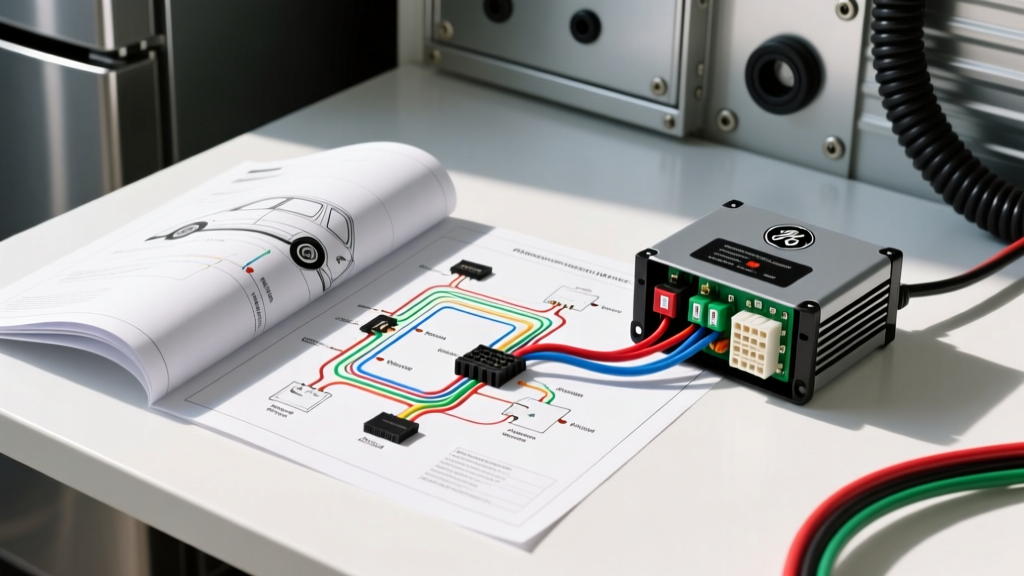
The Challenge: Residential Appliances in Mobile DC Systems
When upfitting a custom camper van, expedition truck, or Class B RV, integrating residential appliances into a mobile DC electrical architecture requires a deep understanding of both AC appliance schematics and automotive power distribution. Many overland builders opt for high-efficiency residential units due to their superior insulation and internal volume. However, locating and interpreting the exact ge refrigerator wiring diagram pdf for your specific model is critical for mapping the AC compressor's surge requirements to your vehicle's DC-AC inverter system. Unlike native 12V DC compressor fridges, a residential AC unit relies on a start relay, run capacitor, and defrost heater that can wreak havoc on an undersized vehicle alternator or poorly wired lithium battery bank.
This advanced technical guide bridges the gap between appliance-level AC schematics and vehicle-level DC wiring, focusing on heavy-duty inverter integration, ignition-sense relay logic, and preventing catastrophic voltage drops across long-wheelbase vans like the Ford Transit or Mercedes-Benz Sprinter.
Decoding the Appliance Schematic: Compressor and Defrost Logic
Before connecting the refrigerator to your vehicle's 3000W pure sine wave inverter, you must analyze the appliance's internal wiring. The GE schematic typically outlines three primary high-draw circuits: the compressor motor, the condenser fan, and the defrost heater.
Compressor Start Relay and PTC Thermistor
The compressor is the most critical load. Most modern GE units utilize a PTC (Positive Temperature Coefficient) thermistor start relay rather than a traditional mechanical current relay. When reviewing the wiring diagram, you will note the main AC line (Black wire) and Neutral (White wire) feeding into the overload protector, then branching to the PTC relay. The PTC relay engages the start winding of the compressor for a fraction of a second to generate the torque required to overcome initial refrigerant head pressure.
Automotive Integration Note: Modified sine wave inverters output a stepped square wave that causes the PTC thermistor to overheat and fail prematurely, as the harmonic distortion prevents the relay from cooling and resetting between compressor cycles. You must specify a Pure Sine Wave inverter with a minimum continuous rating of 3000W to handle the 1.5A RLA (Run Load Amps) and the 12A-15A LRA (Locked Rotor Amps) surge without triggering the inverter's low-voltage cutoff.
Defrost Heater and Ignition Cutoff
The defrost heater typically draws 300W to 450W and activates via a mechanical or electronic timer every 8 to 12 hours. In a mobile environment, if the vehicle's engine is off and the house battery bank is depleted, the defrost heater will continue to pull current until the inverter's low-battery alarm triggers. To prevent deep-discharging a lithium LiFePO4 bank or damaging AGM cells, automotive upfitters wire an ignition-sense relay to sever the inverter's remote ON/OFF circuit when the chassis engine is not running.
Sizing the Vehicle-Side Inverter and DC Wiring
Wiring the DC side of the inverter requires adherence to strict automotive electrical standards. The massive current draw during the compressor's LRA surge (which can momentarily pull over 150A DC from a 12V battery bank) demands oversized cabling to prevent voltage drop. According to SAE J1128 standards for low-tension primary cable, wire gauge must be calculated based on total round-trip length, not just the positive run.
AWG Specifications for High-Surge Inverter Feeds
In a long-wheelbase Ford Transit (148" wheelbase), the battery bank is often located in the rear cargo area, while the inverter may be mounted near the chassis frame rail to keep AC wire runs short. A 15-foot round-trip DC cable run carrying 250A peak requires 2/0 AWG stranded copper welding cable. Using standard 4 AWG wire in this scenario will result in a voltage drop exceeding 3%, causing the inverter to read 11.2V during compressor startup and immediately fault out with a 'Low DC Voltage' error.
| Inverter Size | Max DC Surge | Round-Trip Length | Required AWG | Overcurrent Protection |
|---|---|---|---|---|
| 2000W | 180A | Under 10 ft | 2 AWG | 250A ANL Fuse |
| 3000W | 280A | Under 10 ft | 1/0 AWG | 300A Class-T Fuse |
| 3000W | 280A | 10 - 20 ft | 2/0 AWG | 300A Class-T Fuse |
| 4000W | 350A | Any Length | 4/0 AWG | 400A Class-T Fuse |
Always terminate 2/0 AWG cables with heavy-duty copper lugs crimped using a hydraulic press, and seal the connections with adhesive-lined heat shrink. Torque the inverter busbar nuts to the manufacturer's specification (typically 12-15 ft-lbs for 5/16" hardware) to prevent high-resistance hot spots.
Interfacing the Defrost Timer with Vehicle Ignition Sense
To automate the inverter's standby mode and protect the vehicle's auxiliary battery bank, we interface the inverter's remote control terminals with the vehicle's PCM (Powertrain Control Module) or Upfitter module. For this example, we will use the Ford Transit Upfitter Body Builder Layout Book (Ford Truck BBAS) as our reference.
Wiring the Bosch Ignition Cutoff Relay
The Ford Transit provides an 'Ignition ON' 12V signal at the auxiliary body builder connector (typically a Light Green with Yellow Stripe wire). We use this low-current signal to trigger a heavy-duty automotive relay that controls the inverter's remote switch.
- Relay Selection: Use a high-quality Bosch-style 5-pin relay (e.g., Bosch 0 332 209 150) rated for 40A continuous.
- Pin 86 (Coil +): Connect to the Ford Transit Ignition Sense wire via a Posi-Tap connector.
- Pin 85 (Coil -): Connect to a clean chassis ground point. Ensure the ground stud is sanded to bare metal and treated with dielectric grease.
- Pin 30 (Common): Connect to a fused 12V constant source from the house battery busbar.
- Pin 87 (Normally Open): Connect to the positive remote terminal on the inverter.
When the vehicle's key is turned to the 'ON' position or the engine is running, the PCM sends 12V to Pin 86, energizing the coil and closing the circuit between Pin 30 and 87. This signals the inverter to turn on, allowing the GE refrigerator to run. When you turn the vehicle off to park for the night, the relay de-energizes. However, to allow the fridge to run while camping, a manual override toggle switch should be wired in parallel with Pin 86, drawing 12V from the house bank to keep the inverter active independently of the chassis ignition.
Real-World Troubleshooting: Compressor Stall and Chassis Grounding
Integrating residential AC appliances into a metal vehicle chassis introduces unique grounding challenges. A common failure mode is the inverter's internal GFCI (Ground Fault Circuit Interrupter) tripping the moment the GE compressor's run capacitor engages.
Floating Neutrals and Chassis Bonds
Unlike a residential home where the Neutral and Ground are bonded at the main service panel, a vehicle's inverter often operates with a 'floating neutral.' If the GE refrigerator's internal wiring diagram indicates a ground fault sensor on the compressor housing, the stray capacitance of the vehicle's metal chassis can trick the inverter into detecting a ground fault. According to Victron Energy Wiring Guidelines, resolving this requires creating a temporary Neutral-to-Ground bond inside the inverter's AC output junction box or utilizing an isolation transformer if the vehicle is frequently connected to shore power.
Diagnostic Checklist for Inverter Faults
- Symptom: Inverter clicks off exactly 3 seconds after the fridge compressor attempts to start.
Fix: Measure DC voltage at the inverter busbars during the click. If it drops below 10.5V, your 2/0 AWG wire run is too long, or the battery BMS is restricting discharge current. Upgrade to 4/0 AWG or parallel a second battery bank. - Symptom: Fridge compressor hums but fails to spin, eventually tripping the PTC overload.
Fix: Verify the inverter is outputting a true Pure Sine Wave. Check the AC voltage at the fridge plug; if it is below 110V AC under load, the voltage drop on the 12 AWG AC extension cord is starving the compressor start winding. - Symptom: House battery drains overnight despite the ignition cutoff relay.
Fix: Test the Bosch relay Pin 87a (Normally Closed). If the relay is wired incorrectly or failing, it may be back-feeding 12V into the inverter's remote circuit, keeping the internal logic board awake and drawing a 2A parasitic phantom load.
Mastering the translation between a standard GE appliance schematic and a custom automotive DC architecture ensures reliable off-grid refrigeration without compromising the vehicle's starting battery or sensitive CAN-bus electronics.