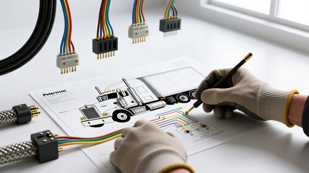
The Reality of Sourcing a Peterbilt Wiring Diagram Free of Charge
When owner-operators and fleet technicians search for a peterbilt wiring diagram free of charge, they are often met with fragmented schematics, outdated forum PDFs, or generic trailer wiring charts. Heavy-duty Class 8 trucks like the Peterbilt 389, 579, and 388 utilize a complex hybrid electrical architecture. While the engine harness (such as the PACCAR MX-13 or Cummins ISX15) relies on proprietary, gated OEM multiplexing, the chassis, lighting, and auxiliary circuits strictly adhere to standardized SAE J1128 and SAE J1129 color codes and routing practices.
As an automotive electrical expert, I can tell you that 80% of all Peterbilt chassis electrical faults—ranging from blown clearance lights to PTO solenoid failures—can be diagnosed without a proprietary dealer-level schematic. By understanding standard heavy-duty wire color codes, AWG (American Wire Gauge) specifications, and connector pinouts, you can build your own mental wiring diagram. Below is a comprehensive, step-by-step troubleshooting flow designed for Peterbilt Class 8 chassis electrical systems.
Step 1: Map the Circuit Using Standard SAE Color Codes
Even if you are using a basic or free generic Class 8 wiring diagram, Peterbilt follows standard Technology & Maintenance Council (TMC) and SAE color conventions for chassis and trailer circuits. Before grabbing a multimeter, identify the circuit's baseline specifications using the reference chart below.
| Circuit Function | Standard Wire Color | Typical AWG Size | Common Fuse / Breaker Rating |
|---|---|---|---|
| Battery Constant 12V (Main Feed) | Red | 8 AWG to 4 AWG | Mega Fuse (150A - 300A) |
| Chassis Ground | White | 10 AWG to 2 AWG | N/A (Direct to Frame/Battery) |
| Tail, Clearance, and Marker Lights | Brown | 18 AWG to 14 AWG | 10A - 15A ATO/Mini |
| Left Turn / Stop Lamp | Yellow | 14 AWG | 15A - 20A |
| Right Turn / Stop Lamp | Green | 14 AWG | 15A - 20A |
| Auxiliary / PTO Solenoid Feed | Blue or Black | 12 AWG | 20A - 30A |
| Ignition Switched (Run/Crank) | Yellow/Red Stripe | 14 AWG | 10A - 15A |
Note: Always verify wire gauge against physical harness thickness. A degraded 14 AWG wire pulling 18 amps for a heated mirror will cause a voltage drop and eventual melting of the Deutsch connector housing.
Step 2: The Step-by-Step Voltage Drop Diagnostic Flow
Never rely solely on a test light for Peterbilt diagnostics. Modern SmartNode multiplex systems and sensitive PACCAR engine control modules (ECMs) can be damaged by the high current draw of incandescent test lights. Always use a high-impedance Digital Multimeter (DMM). Follow this decision tree to isolate the fault.
Phase A: Verify the Power Source (The 50% Rule)
- IF the component (e.g., right-side cab marker light) is completely dead:
THEN set your DMM to DC Volts. Place the red probe on the Brown (marker) wire at the component connector and the black probe on a known good frame ground.
RESULT 1: Reading is 12.4V - 12.8V. Power is reaching the component. The fault is a bad LED module or a localized ground issue. Proceed to Phase B.
RESULT 2: Reading is below 11.5V or 0V. You have an open circuit or high resistance upstream. Proceed to Phase C.
Phase B: Isolate the Ground Fault
- IF power is present but the component fails to illuminate:
THEN perform a ground-side voltage drop test. Place the red probe on the battery positive terminal and the black probe on the component's ground terminal (White wire) while the circuit is loaded (switched ON).
RESULT: A reading above 0.2V indicates excessive resistance at the frame ground stud. Remove the ground ring terminal, clean the chassis paint/corrosion with a wire brush, apply dielectric grease, and re-torque to 15 lb-ft.
Phase C: Locate the Upstream Open or Short
- IF power is missing at the component:
THEN move upstream to the fuse panel or SmartNode output. Probe the output side of the corresponding fuse.
RESULT 1: 12V present at the fuse, but not at the component. You have a broken wire, a corroded bulkhead connector, or a failed intermediate splice. Perform a continuity test (Ohms) with the battery disconnected.
RESULT 2: 0V at the fuse. Check the multiplex node inputs (switch signal) or the main battery feed to the fuse block.
Step 3: Inspecting High-Failure Connectors and Terminals
Peterbilt utilizes specific weather-pack connectors for chassis and engine harnesses. The most common failure mode in Class 8 trucks is not a broken wire, but terminal fretting corrosion inside the connector housing. This occurs when micro-vibrations cause the male and female terminals to rub, stripping the tin/lead plating and exposing copper to moisture.
| Connector Type | Common Application | Terminal Size / AWG | Extraction Tool Required |
|---|---|---|---|
| Deutsch DT (4-Pin) | Headlights, Tail lamps, ABS | Size 16 (14-18 AWG) | Deutsch DT Wedge Tool (Red) |
| Deutsch DTM (12-Pin) | SmartNode I/O, Cab switches | Size 20 (18-22 AWG) | Deutsch DTM Wedge Tool (Green) |
| Metri-Pack 280 | Sensors, ECM inputs, Relays | 2.8mm Blade (14-18 AWG) | Metri-Pack 280 Release Tool |
| Metri-Pack 630 | Alternator, Starter, High Amp | 6.3mm Blade (8-12 AWG) | Metri-Pack 630 Release Tool |
Expert Troubleshooting Tip: If you are probing a Deutsch DT connector on a Peterbilt 389 headlight harness, never force standard T-pins into the front of the connector. This will spread the female terminal tines, causing a permanent intermittent connection. Always back-probe the wire seal using a specialized back-probe pin, or carefully extract the terminal using the correct colored wedge removal tool.
Step 4: Navigating Peterbilt Multiplexed Nodes (SmartNode & REO)
Modern Peterbilt models (especially the 579 and newer 389 variants) use multiplexing to reduce harness weight and copper volume. The SmartNode system acts as a localized power distribution module. Instead of running heavy 10 AWG wires from the dash to the roof marker lights, a thin 18 AWG CAN bus or LIN bus signal tells the SmartNode to trigger an internal solid-state relay (SSR).
Troubleshooting Multiplex Outputs
- Scan for Active Faults: Connect a J1939 compliant diagnostic tool (like NEXIQ or OTR tool). Look for Body Controller (BC) or SmartNode SPN (Suspect Parameter Number) codes indicating an 'Open Load' or 'Short to Ground'.
- Check the Switch Input: Multiplex nodes require a valid switch input (usually a ground signal via a 2.2k ohm pull-up resistor) to trigger the high-current output. Verify the switch is sending the correct logic signal to the node input pin.
- Verify Node Power and Ground: A SmartNode cannot output 12V to a clearance light if its main 8 AWG Red battery feed or 4 AWG White ground has a voltage drop. Perform a loaded voltage drop test on the node's main power and ground pins.
- Inspect the J1939 CAN Bus Backbone: If multiple unrelated systems (e.g., dash gauges, ABS, and roof lights) are failing simultaneously, suspect a CAN bus fault. Measure the resistance across the CAN High and CAN Low pins at the diagnostic connector. With the ignition OFF and batteries disconnected, you should read exactly 60 ohms (representing two 120-ohm terminating resistors in parallel). A reading of 120 ohms means a terminating resistor is missing or a backbone wire is severed.
Step 5: Safely Probing PACCAR MX-13 Engine Harnesses
When your troubleshooting moves from the chassis to the engine bay, the rules change. The PACCAR MX-13 engine harness uses highly sensitive 5V reference circuits for sensors (like the Camshaft Position Sensor and DEF tank temperature sensors). Never use a test light or standard 12V jumper wire on engine sensor circuits. Furthermore, engine harness wires are often shielded (drain wires wrapped in foil). If a free wiring diagram shows a shielded wire (often denoted by a dashed outer circle or a specific 'SHLD' pinout on the ECM connector), ensure the drain wire is grounded only at the ECM side to prevent ground loops and electromagnetic interference (EMI) from the alternator.
Sources and Further Technical Reference
While finding a complete, up-to-date Peterbilt wiring diagram free of charge is nearly impossible due to OEM intellectual property protections, adhering to industry standards will allow you to troubleshoot 90% of heavy-duty electrical faults safely and accurately. For official wiring schematics, multiplex logic charts, and ECM pinouts, technicians should utilize authorized dealer portals or subscribe to professional service databases.
- SAE International J1128 - Standard for heavy-duty vehicle wiring color codes and insulation requirements.
- Technology & Maintenance Council (TMC) - Recommended Practices (RP) for Class 8 electrical system installations and grounding.
- Peterbilt Parts and Service - Official OEM resource for authorized wiring schematic access and SmartNode configuration software.