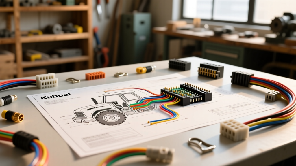
The Critical Role of OEM Schematics in Heavy Equipment
When servicing compact and utility tractors, accessing a high-resolution schematic Kubota wiring diagram PDF is the difference between a two-hour repair and a two-week headache. Unlike standard passenger vehicles, agricultural and landscaping equipment operates in high-vibration, high-moisture environments where electrical harnesses are subjected to severe mechanical stress. Aftermarket wiring guides often omit crucial safety interlock circuits or proprietary sensor pinouts. By utilizing the official factory schematic, technicians can accurately trace the 12V DC negative-ground system, diagnose the Operator Presence Interlock Controller (OPIC), and verify alternator excitation circuits without resorting to destructive wire piercing.
Decoding the Kubota PDF Matrix System
Kubota electrical schematics do not use the linear left-to-right routing found in some automotive diagrams. Instead, they employ an alphanumeric grid matrix system. When you open your schematic Kubota wiring diagram PDF, you will notice letters across the top axis (A, B, C) and numbers down the vertical axis (1, 2, 3).
Every wire, connector, and ground point is assigned a specific coordinate. For example, a wire originating at coordinate B2 and terminating at D5 will have a destination marker printed on the schematic. This allows technicians to jump across multi-page PDF layouts without losing the trace path. Furthermore, Kubota designates connectors with a 'CN' prefix (e.g., CN1, CN2) and ground points with a 'GND' or specific bolt-torque designation.
Standard Kubota Wire Color and Gauge Specifications
Before probing any circuit with a digital multimeter (DMM), you must understand the manufacturer's color-coding shorthand. In the PDF legend, colors are abbreviated. Below is the definitive translation of Kubota's primary wire colors and their typical American Wire Gauge (AWG) applications based on SAE J1128 Low Tension Primary Cable standards.
| Abbreviation | Color | Typical AWG | Primary Circuit Application |
|---|---|---|---|
| R | Red | 8 to 10 AWG | Battery Positive (Always Hot), Starter Feed |
| B | Black | 8 to 12 AWG | Primary Chassis Ground, Battery Negative |
| W | White | 12 to 14 AWG | Switched Ignition, Accessory Power |
| Y | Yellow | 14 to 16 AWG | Lighting Circuits, Hazard Flashers |
| SB | Sky Blue | 16 to 18 AWG | Alternator Sense / Excitation, Sensor Signals |
| G | Green | 14 to 16 AWG | Instrument Cluster Illumination, CAN-Low (Newer Models) |
| Br | Brown | 16 AWG | Parking Lights, Marker Lamps |
Note: Tracer wires are denoted with a slash. A 'W/R' wire is White with a Red tracer stripe.
Main Chassis Connector (CN1) Pinout Walkthrough
The CN1 connector serves as the primary bridge between the engine-side harness and the chassis/dashboard harness. Corrosion or pin push-out at CN1 is responsible for over 40% of intermittent electrical faults in the B-Series and L-Series tractors. Below is a standard pinout configuration for a 6-pin CN1 weather-pack style connector.
| Pin | Wire Color | AWG | Function / Destination |
|---|---|---|---|
| 1 | R | 10 | Main Battery Feed to Key Switch (Always Hot) |
| 2 | B | 10 | Main Harness Ground to Chassis Star Point |
| 3 | W/R | 14 | Starter Solenoid Signal (from Key Switch 'ST' position) |
| 4 | W | 12 | Key Switch 'ON' / Ignition Feed to OPIC Relay |
| 5 | G/W | 16 | PTO Safety Interlock Switch Signal |
| 6 | SB | 16 | Alternator Sense Wire (Direct Battery Voltage Feedback) |
Tracing the Safety Interlock Circuit
One of the most complex sections of any schematic Kubota wiring diagram PDF is the safety interlock system. Modern Kubota tractors utilize a relay-logic network (or a dedicated OPIC module) to prevent the engine from cranking unless the HST (Hydrostatic Transmission) pedals are in neutral, and to kill the engine if the operator leaves the seat while the PTO is engaged.
Seat Switch and PTO Relay Logic
The seat switch is a normally-open (NO) switch that closes under the weight of the operator (typically requiring >40 lbs of force). When the operator stands up, the switch opens. If the PTO clutch switch is in the 'ON' position, this open circuit de-energizes the main fuel stop solenoid relay.
To test this circuit without replacing parts:
- Disconnect the 2-pin connector at the base of the seat pan.
- Set your DMM to the Ohms (Ω) setting.
- With no weight on the seat, the meter should read OL (Open Loop).
- Apply firm hand pressure to the seat cushion; the meter should drop to less than 2.0 Ω.
- If the reading fluctuates, the internal diaphragm is failing, requiring a complete switch replacement.
Common Electrical Faults & Multimeter Diagnostics
Even with a perfect schematic Kubota wiring diagram PDF in hand, physical degradation causes faults that the diagram cannot predict. Here are the three most common failure modes and how to diagnose them.
1. Alternator Sense Wire (SB) Chafing
Symptom: The battery slowly drains over a week of use, or the alternator overcharges and boils the battery electrolyte.
Cause: The Sky Blue (SB) sense wire on Pin 6 of CN1 routes near the steering column. Vibration causes the wire insulation to chafe against the steel column bracket, creating a parasitic draw or altering the voltage feedback to the alternator regulator.
Fix: Perform a voltage drop test on the SB wire. With the engine running at 1500 RPM, probe the alternator sense terminal and the positive battery post. The difference should be less than 0.1V. If higher, repair the harness and apply dielectric grease to the connector cavity as recommended by Kubota support documentation.
2. Engine Block Ground Strap Corrosion
Symptom: Slow cranking, dim headlights, and erratic fuel solenoid behavior despite a fully charged battery.
Cause: The heavy 8 AWG Black (B) ground cable connects the negative battery terminal to the engine block. Because the engine is mounted on rubber vibration isolators, this strap carries the entire starter return current. Corrosion under the ring terminal increases resistance.
Fix: Remove the M8 ground bolt. Clean the block mating surface with a wire wheel down to bare metal. Apply a thin layer of anti-seize compound (not dielectric grease, which is an insulator) to the bare metal, reinstall the terminal, and torque the M8 bolt to 18-22 Nm.
3. HST Neutral Start Switch Misalignment
Symptom: The tractor will not crank, but jumping the starter solenoid manually engages the engine. All safety relays test good.
Cause: The HST pedal neutral switch is a mechanical micro-switch activated by the pedal linkage rod. Over time, the linkage stretches, preventing the switch plunger from fully depressing when the pedals are centered.
Fix: Consult the mechanical adjustment section of the PDF. Loosen the 10mm locknut on the switch actuator rod and adjust the threaded collar until you hear a distinct 'click' when the pedal is within 5mm of the neutral detent.
Best Practices for Harness Repair
When your schematic Kubota wiring diagram PDF leads you to a broken wire, never use twist-on wire nuts or standard electrical tape. The engine bay environment will destroy these repairs within weeks. Always use adhesive-lined marine-grade heat shrink terminals. For wires carrying over 10 Amps (such as the PTO clutch feed or lighting circuits), use an open-barrel crimp tool rather than soldering. Soldered joints become brittle under the high-frequency vibration of a diesel engine, leading to micro-fractures and eventual open circuits. By combining the precision of the OEM schematic with aerospace-grade repair techniques, you ensure the tractor's electrical system remains reliable for thousands of operational hours.