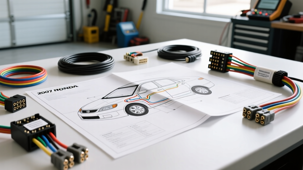
Introduction to the 2007 Honda Accord Electrical System
Diagnosing electrical faults in the 7th-generation Honda Accord requires more than just a basic multimeter; it demands a systematic approach guided by the factory 2007 Honda Accord wiring diagram. Whether you are working on the 2.4L K24 inline-four or the 3.0L J30 V6, Honda’s multiplexed electrical networks and strict metric wire sizing mean that guessing is not an option. This guide provides a professional, step-by-step troubleshooting flow to help you isolate shorts, open circuits, and module communication failures using OEM schematic data.
Phase 1: Preparation and Schematic Navigation
Before touching a single wire, you must understand how Honda structures its service manuals. Unlike domestic manufacturers that often bundle diagrams by system, the 2007 Honda Accord wiring diagram is typically organized by circuit function and connector index.
- Metric Wire Sizing: Honda uses metric cross-sectional areas rather than American Wire Gauge (AWG). You will see designations like 0.5f, 0.85f, 1.25f, and 2.0f. These translate roughly to 20, 18, 16, and 14 AWG, respectively. Always match your replacement wire to the metric specification to prevent voltage drop.
- Shielded Wiring: When referencing the 2007 Accord schematic, look for the zig-zag line overlaying a wire. This indicates a shielded cable, heavily used for the Crankshaft Position (CKP) and Camshaft Position (CMP) sensors to prevent electromagnetic interference (EMI) from the ignition coils.
- Connector Views: Honda diagrams show connectors from the terminal insertion side (wire side), not the mating face. Always verify your pinout orientation before back-probing.
Phase 2: Step-by-Step Diagnostic Flow
When facing a symptom like a no-start condition, an inoperative fuel pump, or a persistent Check Engine Light, follow this sequential troubleshooting flow to isolate the fault.
Step 1: Verify Power and Ground at the Component
Never assume a component is dead until you have verified the circuit at the component’s connector. Disconnect the harness and use a digital multimeter (DMM) set to DC Volts.
- Connect the DMM’s black lead to a known-good engine ground (such as the alternator casing).
- Back-probe the power supply pin with the red lead. For a fuel pump relay output, you should see battery voltage (12.2V - 12.6V) for exactly 2 seconds when the key is turned to the ON (II) position.
- If voltage is present, switch the DMM to Ohms. Measure the resistance between the component’s ground pin and the chassis. A reading above 0.5 ohms indicates a corroded ground path.
Step 2: Trace the Harness to the PCM or MICU
If power or ground is missing at the component, consult the 2007 Honda Accord wiring diagram to trace the circuit back to its source. For engine management, this is the Powertrain Control Module (PCM). For body accessories, it is the Multiplex Integrated Control Unit (MICU).
Critical Rule: Never pierce wire insulation with test probes. Piercing exposes the copper strands to moisture, leading to capillary wicking and green corrosion inside the harness. Always use dedicated back-probing pins or T-pin adapters at the connector terminals.
Step 3: Perform Voltage Drop Testing
A standard continuity test will not reveal a high-resistance fault under load. Perform a voltage drop test across the entire length of the suspect wire. Place one DMM lead at the battery positive terminal and the other at the PCM power feed pin. With the circuit loaded, a voltage drop greater than 0.1V per connection or 0.2V across the wire length indicates a failing splice or corroded terminal.
2007 Honda Accord PCM Connector Pinout Reference
The 2.4L K-series and 3.0L J-series engines utilize a multi-connector PCM setup. Below is a critical reference table for PCM Connector B (24-Pin), which handles fuel injection and ignition power feeds. Wire colors listed are standard OEM Honda codes.
| Pin | Function | Wire Color | Wire Size (Metric) | Diagnostic Note |
|---|---|---|---|---|
| B1 | IGP1 (Ignition Power) | BLK/YEL | 1.25 | Supplies power to PCM drivers. Check if stalling when hot. |
| B2 | IGP2 (Ignition Power) | BLK/YEL | 1.25 | Secondary PCM logic feed. Tied to PGM-FI main relay. |
| B3 | INJ1 (Injector #1) | YEL/BLK | 0.85 | PCM provides the ground path to fire the injector. |
| B4 | INJ2 (Injector #2) | YEL/BLU | 0.85 | Check for 12V reference; PCM pulses ground. |
| B5 | INJ3 (Injector #3) | YEL/GRN | 0.85 | Verify no short to ground in harness. |
| B6 | INJ4 (Injector #4) | YEL/RED | 0.85 | Common failure point for chafing near valve cover. |
| B13 | PG1 (PCM Ground) | BLK | 2.0 | Terminates at G101 (Thermostat housing). Clean if codes P0107/P0108 appear. |
Phase 3: Diagnosing Common 2007 Accord Electrical Gremlins
The 2003-2007 Accord generation is notorious for a few specific electrical failure modes. Use the wiring diagram to target these known weak points.
Symptom: Intermittent Stalling or No-Start (PGM-FI Relay)
The PGM-FI (Programmed Fuel Injection) Main Relay 1 and 2 are located in the under-hood fuse box. Relay 1 powers the PCM and injectors, while Relay 2 powers the fuel pump. If the vehicle cranks but won't start, and the fuel pump does not prime, consult the diagram for the BLK/YEL (Black/Yellow) wire feeding the PGM-FI relay coil. The ground path for this relay coil is controlled by the PCM immobilizer logic. If the green key light flashes on the dash, the immobilizer is cutting the ground path via the MICU.
Symptom: Parasitic Battery Draw (MICU Failure)
The Multiplex Integrated Control Unit (MICU) is built directly into the under-dash fuse/relay box. It controls the power windows, door locks, and interior lighting. A very common failure on the 2007 Accord is cracked solder joints on the MICU internal circuit board, causing the unit to stay "awake" and drain the battery overnight.
Diagnostic Flow: Pull the under-dash fuses one by one while monitoring a DMM set to DC Amps (10A scale) connected in series with the negative battery terminal. If pulling a specific MICU-controlled circuit drops the parasitic draw from 1.5A down to the normal 30mA-50mA range, the MICU board requires resoldering or the entire under-dash fuse box must be replaced.
Symptom: CAN-Bus Communication Errors (U0100, U0122)
The 2007 Accord utilizes a high-speed Controller Area Network (CAN) bus for module-to-module communication. The Data Link Connector (DLC) under the driver's dash is your access point.
- Pin 6: CAN-High (typically Red or White wire)
- Pin 14: CAN-Low (typically Green or Blue wire)
With the battery disconnected, measure the resistance between DLC Pin 6 and Pin 14. The 2007 Honda Accord wiring diagram shows two 120-ohm terminating resistors in parallel (one in the PCM, one in the MICU or gauge cluster). Your DMM should read exactly 60 ohms. If you read 120 ohms, one module is disconnected or a wire is broken. If you read near 0 ohms, the CAN bus wires are shorted together.
Advanced Wire Repair and Splicing Standards
When the 2007 Honda Accord wiring diagram leads you to a broken wire, do not use twist-on connectors or standard electrical tape. According to SAE J1128 Wire Standards, automotive repairs must withstand high heat and vibration. Use adhesive-lined heat shrink solder seal connectors. For shielded wires (like the CKP sensor), you must strip back the shielding, repair the inner signal wire, and then bridge the outer shielding mesh using a dedicated copper shield repair wrap to maintain EMI protection.
Authoritative References
For complete, model-specific circuit routing and connector terminal views, always cross-reference your findings with official documentation:
- Honda OEM TechInfo Service Portal - The official source for factory service manuals and interactive wiring schematics.
- Haynes Honda Accord Repair Manuals - Excellent for physical component locations and ground point mapping (e.g., G101, G401).
- SAE International J1128 - Standards for low-tension primary cable and wire repair methodologies.