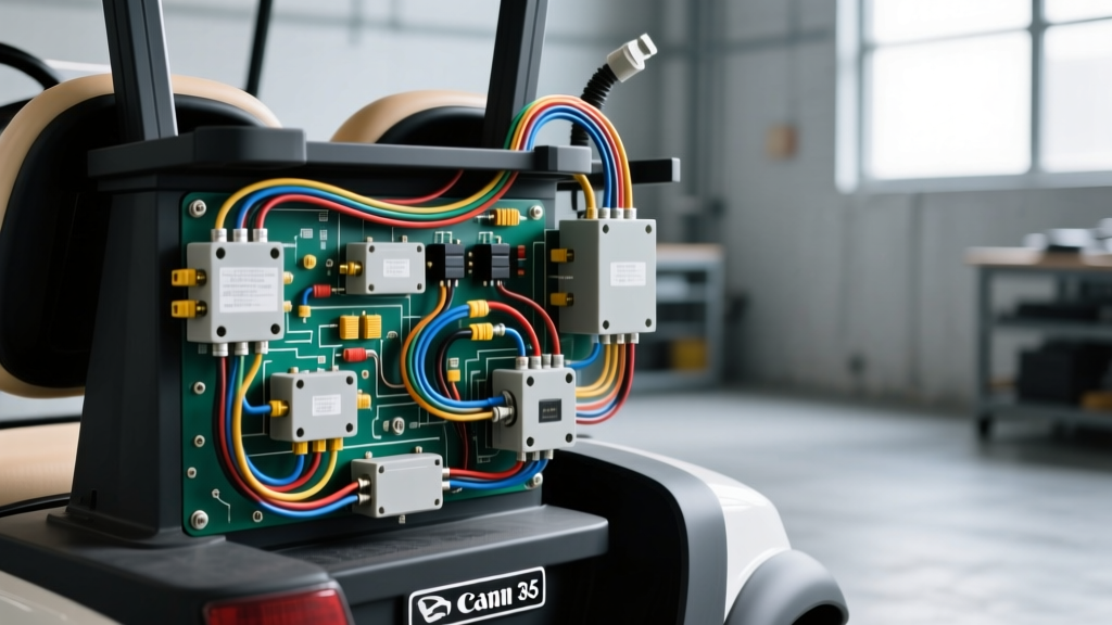
Decoding the Club Car Wiring Diagram 36 Volt Architecture
When tackling an upgrade project on a classic 36-volt electric golf cart, understanding the baseline electrical architecture is non-negotiable. The stock Club Car wiring diagram 36 volt system (specifically the 1996-2014 DS platform) relies on a series-wound or ADC motor, a heavy-duty solenoid, and a V-Glide or MCOR throttle assembly. Whether you are dropping in a modern 36V LiFePO4 lithium battery pack or integrating high-draw 12V accessories, modifying the factory harness requires strict adherence to AWG sizing, proper fusing, and an understanding of the controller's logic circuits.
In this modification guide, we will break down the factory 36V power loop, outline the exact wiring schematics for a lithium BMS (Battery Management System) integration, and detail the installation of a DC-DC step-down converter for auxiliary accessories.
Stock 36V Power Loop & Wire Color Reference
The factory Club Car DS 36V harness utilizes specific color codes for high-current and low-current logic circuits. Before cutting or splicing, verify your cart's year, as pre-1996 resistor-box carts differ significantly from the 1996+ solid-state controller models. Below is the standard wire color reference for a 1996-2001 V-Glide 36V system:
| Circuit Function | Stock Wire Color | Typical AWG | Connection Point |
|---|---|---|---|
| Main Battery Positive (B+) | Red | 2 AWG | Battery Pack (+) to F/R Switch |
| Main Battery Negative (B-) | Black | 2 AWG | Battery Pack (-) to Motor A2 / Controller B- |
| Solenoid High Side | Red (Heavy) | 4 AWG | F/R Switch to Solenoid Large Post |
| Solenoid Activation (+) | Red/White Tracer | 16 AWG | Key Switch to Solenoid Small Post |
| Solenoid Activation (-) | Yellow | 16 AWG | Controller / Throttle Microswitch |
| V-Glide Throttle Signal | Black/White | 18 AWG | Throttle Box to Controller Pin |
The Upgrade Project: 36V LiFePO4 Lithium Conversion
Upgrading from six 6V lead-acid batteries to a single 36V (nominal 38.4V) LiFePO4 pack drastically reduces weight and increases usable amperage. However, the factory wiring diagram must be modified to accommodate the BMS. The most common failure mode in DIY lithium swaps is the BMS entering 'sleep mode' while driving, instantly cutting power to the motor and locking the brakes.
BMS Integration & Pre-Charge Circuit Wiring
To prevent the BMS from sleeping and to protect the controller's internal capacitors from inrush current, you must wire a pre-charge circuit and a BMS 'wake/enable' signal.
- Main Power Routing: Run 1/0 AWG welding cable from the BMS Main Discharge Negative terminal directly to the cart's main negative busbar. Do not route this through the factory ammeter shunt, as the high burst current (up to 300A) of a lithium pack will melt the stock shunt.
- The Pre-Charge Resistor: Solder a 47-ohm, 10-watt pre-charge resistor across the two large terminals of the main 36V solenoid. When the key is turned on, the microswitches close, allowing a small current to flow through the resistor to charge the controller capacitors before the main solenoid engages.
- BMS Wake Signal: Locate the BMS 'Discharge Enable' or 'Wake' wire (usually a thin 20 AWG blue or white wire on the BMS harness). Splice this wire into the cart's Key Switch Output (Red/White wire). This ensures the BMS stays awake as long as the key is in the 'ON' position. If you skip this step, the BMS will time out and shut off the cart mid-drive.
Accessory Modification: Adding a 12V Step-Down Circuit
Adding LED light bars, winches, or USB chargers to a 36V cart requires a DC-DC step-down converter. Never tap into a single 6V battery for 12V accessories; this will severely unbalance the battery pack, causing premature sulfation in lead-acid setups or BMS cell-drift faults in lithium setups.
DC-DC Converter Wiring Specifications
For a 30A 12V accessory load (e.g., light bar and stereo), use an isolated DC-DC converter rated for 30V-60V input.
- Input Wiring (36V Side): Use SAE J1128 compliant 10 AWG primary wire. Connect directly to the main B+ and B- busbars, bypassing the ignition switch so accessories can run without the cart being 'on'. Install an inline 40A ANL fuse on the positive input leg within 6 inches of the busbar.
- Output Wiring (12V Side): Use 12 AWG wire routed to a marine-grade 12V fuse block. Ground the 12V negative directly to the DC-DC converter's output terminal, not the cart's chassis, to prevent ground loop interference with the motor controller's logic signals.
- Heat Dissipation: Mount the DC-DC converter on an aluminum backplate or the cart's aluminum frame rail. These units operate at roughly 85% efficiency; a 30A load will generate roughly 60 watts of heat that must be passively dissipated.
Hardware, AWG, and Torque Specifications
High-current DC circuits are unforgiving of loose connections. A loose battery terminal creates resistance, generating heat that melts the lead post and causes voltage drop, which the controller interprets as a dead battery pack. Follow these strict mechanical specifications during your 36V modification:
| Component / Terminal | Required Wire Gauge | Hardware Type | Torque Specification |
|---|---|---|---|
| Battery Pack Interconnects | 2 AWG or 1/0 AWG | 3/8" Stainless Steel Flange Nut | 95 - 105 in-lbs |
| Motor Terminals (A1, A2, S1, S2) | 4 AWG (Flex) | 5/16" Brass Nut | 70 - 80 in-lbs |
| Solenoid Large Posts | 4 AWG | 3/8" Steel Nyloc Nut | 110 - 120 in-lbs |
| Controller Logic Pins | 18 AWG | Deutsch DT / Amp Connectors | Pin Crimp: Use HDTV-15 Tool |
Pro-Tip: Always apply a thin layer of Noalox (aluminum anti-oxidant paste) to all copper-to-lead and copper-to-aluminum connections to prevent galvanic corrosion, especially in humid environments.
Troubleshooting Common 36V Mod Failures
Even with a perfect schematic, real-world variables can cause faults. Use this diagnostic tree for common post-modification issues:
Symptom: Solenoid Clicks, But Cart Does Not Move
- Cause 1: Controller Low-Voltage Cutoff (LVC) Triggered. If you upgraded to a 36V Lithium pack (which sits at 43.8V fully charged) but the stock Alltrax or Curtis controller is programmed for lead-acid LVC (31.5V), a voltage sag under load might still trigger a fault if the BMS limits output. Fix: Reprogram the controller LVC to match the BMS low-voltage cutoff (typically 30.0V for 12S LiFePO4).
- Cause 2: F/R Microswitch Failure. The Forward/Reverse switch assembly contains two 16A microswitches that signal the controller to engage the solenoid. The copper contacts inside these switches corrode rapidly. Fix: Test for 36V at the solenoid's small yellow wire while pressing the pedal. If absent, replace the F/R microswitches with sealed IP67-rated units.
Symptom: DC-DC Converter Overheating or Flickering Lights
- Cause: High-Frequency EMI Interference. The PWM (Pulse Width Modulation) motor controller generates massive electromagnetic interference (EMI) that can backfeed into the DC-DC converter's input, causing its internal protection circuit to cycle on and off. Fix: Install a 36V inline EMI suppression filter (ferrite core choke) on the DC-DC converter's input positive wire, and ensure the DC-DC chassis is properly grounded.
Final Verification Steps
Before taking the modified 36V Club Car on the road, perform a static voltage drop test. With the cart jacked up and the drive wheels off the ground, engage the throttle to full speed. Using a digital multimeter, measure the voltage drop across every major connection (Battery post to cable lug, cable lug to F/R switch, F/R switch to solenoid). A healthy connection should show a voltage drop of less than 0.05V (50mV). Any reading above 0.10V indicates a high-resistance joint that requires disassembly, wire brushing, and re-torquing.